Optical shaping apparatus and optical shaping method

a technology of optical shaping and shaping apparatus, which is applied in the direction of instruments, manufacturing tools, other domestic objects, etc., can solve the problems of lowering productivity, achieve the effect of suppressing the lowering of productivity, reducing the slicing pitch, and high accuracy

Active Publication Date: 2015-07-23
TOYOTA JIDOSHA KK
View PDF3 Cites 25 Cited by
  • Summary
  • Abstract
  • Description
  • Claims
  • Application Information

AI Technical Summary

Benefits of technology

[0023]The optical shaping apparatus according to this aspect of the present invention does not require the time for letting the optically curing resin liquid flow above the cured resin layer and the time for waiting until the the optically curing resin liquid flowed above the cured resin layer is stabilized, both of which are required in the prior art method. As a result, it is possible to shape a 3D object with high accuracy while suppressing the lowering of the productivity, which would otherwise be caused when the slicing pitch is reduced.
[0024]The optical shaping apparatus preferably further includes a digital mirror device that reflects the first light beam generated by the first light source, in which the firs...

Problems solved by technology

Therefore, there is a problem that as the slicing pitch is reduc...

Method used


Image

  • Optical shaping apparatus and optical shaping method
  • Optical shaping apparatus and optical shaping method
  • Optical shaping apparatus and optical shaping method

Examples


first exemplary embodiment

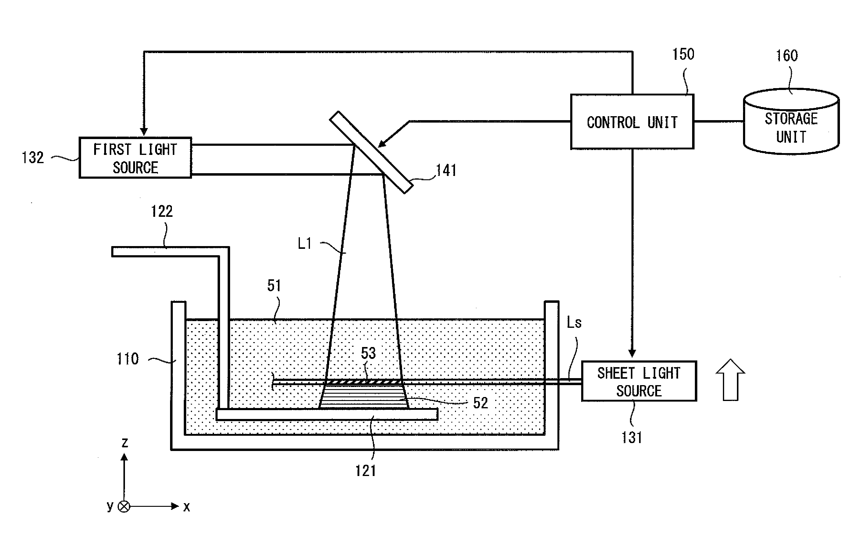
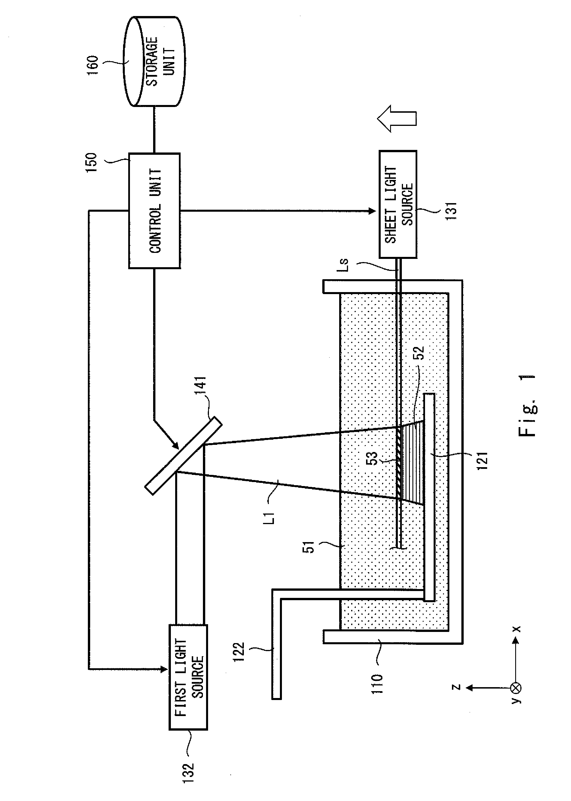
[0033]Firstly, an optical shaping apparatus according to a first exemplary embodiment is explained with reference to FIG. 1. FIG. 1 is a schematic cross section of an optical shaping apparatus according to a first exemplary embodiment. As shown in FIG. 1, the optical shaping apparatus according to the first exemplary embodiment includes a container tank 110, a stage 121, a rod 122, a sheet light source 131, a first light source 132, a digital mirror device (DMD) 141, a storage unit 150, and a control unit 160.

[0034]Note that, needless to say, the right-hand xyz-coordinate system shown in FIG. 1 is shown just for the sake of convenience for explaining the positional relation among the components. In FIG. 1, the xy-plane forms a horizontal plane and the z-axis direction is the vertical direction. More specifically, the positive direction on the z-axis is the vertically upward direction.

[0035]The container tank 110 is a box-shaped tank with an opened top. An optically curing resin liqu...

second exemplary embodiment

[0059]Next, an optical shaping apparatus according to a second exemplary embodiment is explained with reference to FIGS. 4 and 5. FIGS. 4 and 5 are schematic cross sections of optical shaping apparatuses according to a second exemplary embodiment. The optical shaping apparatus according to the second exemplary embodiment includes a second light source 133 and a DMD (Digital Mirror Device) 142 in addition to the components of the optical shaping apparatus according to the first exemplary embodiment. The other configuration of the optical shaping apparatus according to the second exemplary embodiment is similar to that of the optical shaping apparatus according to the first exemplary embodiment, and therefore its detailed explanation is omitted here.

[0060]The second light source 133 is similar to the first light source 132. That is, the second light source 133 includes, for example, a UV-ray lamp and a condensing lens, and emits a light beam (second light beam) L2. The light beam L2 i...


PUM

PropertyMeasurementUnit
Energy densityaaaaaaaaaa

Abstract

An optical shaping method according to the present invention is an optical shaping method for shaping a three-dimensional structure by repeating a process for forming a cured resin layer 53 by irradiating an optically curing resin liquid 51 with light so that cured resin layers 53 are laminated. The process for forming the cured resin layer 53 includes, while applying a sheet light Ls to the optically curing resin liquid 51, applying a first light beam L1 intersecting the sheet light Ls to this optically curing resin liquid, and thereby forming the cured resin layer 53 in an area where the sheet light Ls intersects the first light beam L1. The irradiation place of the sheet light Ls is moved and the process for forming the cured resin layer 53 is repeated.

Description

INCORPORATION BY REFERENCE[0001]This application is based upon and claims the benefit of priority from Japanese patent application No. 2014-9608, filed on Jan. 22, 2014, the disclosure of which is incorporated herein in its entirety by reference.BACKGROUND OF THE INVENTION[0002]1. Field of the Invention[0003]The present invention relates to an optical shaping apparatus and an optical shaping method.[0004]2. Description of Related Art[0005]In recent years, an optical shaping method for shaping a three-dimensional (herein after expressed as “3D”) structure in which a process for selectively forming a cured resin layer by irradiating an optically curing resin liquid with light is repeatedly performed so that a plurality of cured resin layers are laminated has been receiving attention. In such an optical shaping method, a 3D structure is shaped (i.e., manufactured) by creating data of a plurality of cross sections from design data obtained by a 3D CAD (Computer Aided Design) by slicing ...

Claims


Application Information

Patent Timeline
IPC IPC(8): B29C41/22B29D11/00B29C67/00
CPCB29C41/22B29C67/0085B29D11/0073B33Y30/00B33Y10/00B29C64/124B29C64/268B29C64/277
Inventor SARUHASHI, KENFURUKAWA, ISAMUIWAMOTO, KUNIHIROARATA, KONOSUKEASANO, MITSUTOSHITSUBOI, KENTAROUEDA, TETSUJIIKEDA, JUNICHI
Owner TOYOTA JIDOSHA KK
Why Eureka
Try Eureka