Active vibration control system with non-concentric revolving masses

Active Publication Date: 2015-07-23
BELL HELICOPTER TEXTRON INC
View PDF19 Cites 36 Cited by
  • Summary
  • Abstract
  • Description
  • Claims
  • Application Information

AI Technical Summary

Problems solved by technology

The blades cause vibrations that are a function of the rotational speed of the rotor, and aircraft designers have difficulty accurately predicting the exact vibratio

Method used


Image

  • Active vibration control system with non-concentric revolving masses
  • Active vibration control system with non-concentric revolving masses
  • Active vibration control system with non-concentric revolving masses

Examples


Embodiment Construction

[0018]Illustrative embodiments of the system and method of the present disclosure are described below. In the interest of clarity, all features of an actual implementation may not be described in this specification. It will of course be appreciated that in the development of any such actual embodiment, numerous implementation-specific decisions must be made to achieve the developer's specific goals, such as compliance with system-related and business-related constraints, which will vary from one implementation to another. Moreover, it will be appreciated that such a development effort might be complex and time-consuming but would nevertheless be a routine undertaking for those of ordinary skill in the art having the benefit of this disclosure.

[0019]In the specification, reference may be made to the spatial relationships between various components and to the spatial orientation of various aspects of components as the devices are depicted in the attached drawings. However, as will be ...


PUM


Abstract

A vibration control system for a rotor hub provides vibration attenuation in an aircraft by reducing the magnitude of rotor induced vibratory. The system can include a force generating device attached to a rotor hub which rotates along with the rotor at the rotational speed of the rotor. Vibratory shear force is generated by rotating unbalanced weights each about an axis non-concentric with the rotor hub axis at high speed to create large centrifugal forces. The rotational speed of the weights can be a multiple of the rotor rotational speed to create shear forces for canceling rotor induced vibrations. The amplitude of the generated shear force is controlled by indexing the positions of the unbalanced weights relative to each other, while the phase of the shear force is adjusted by equally phasing each weight relative to the rotor.

Description

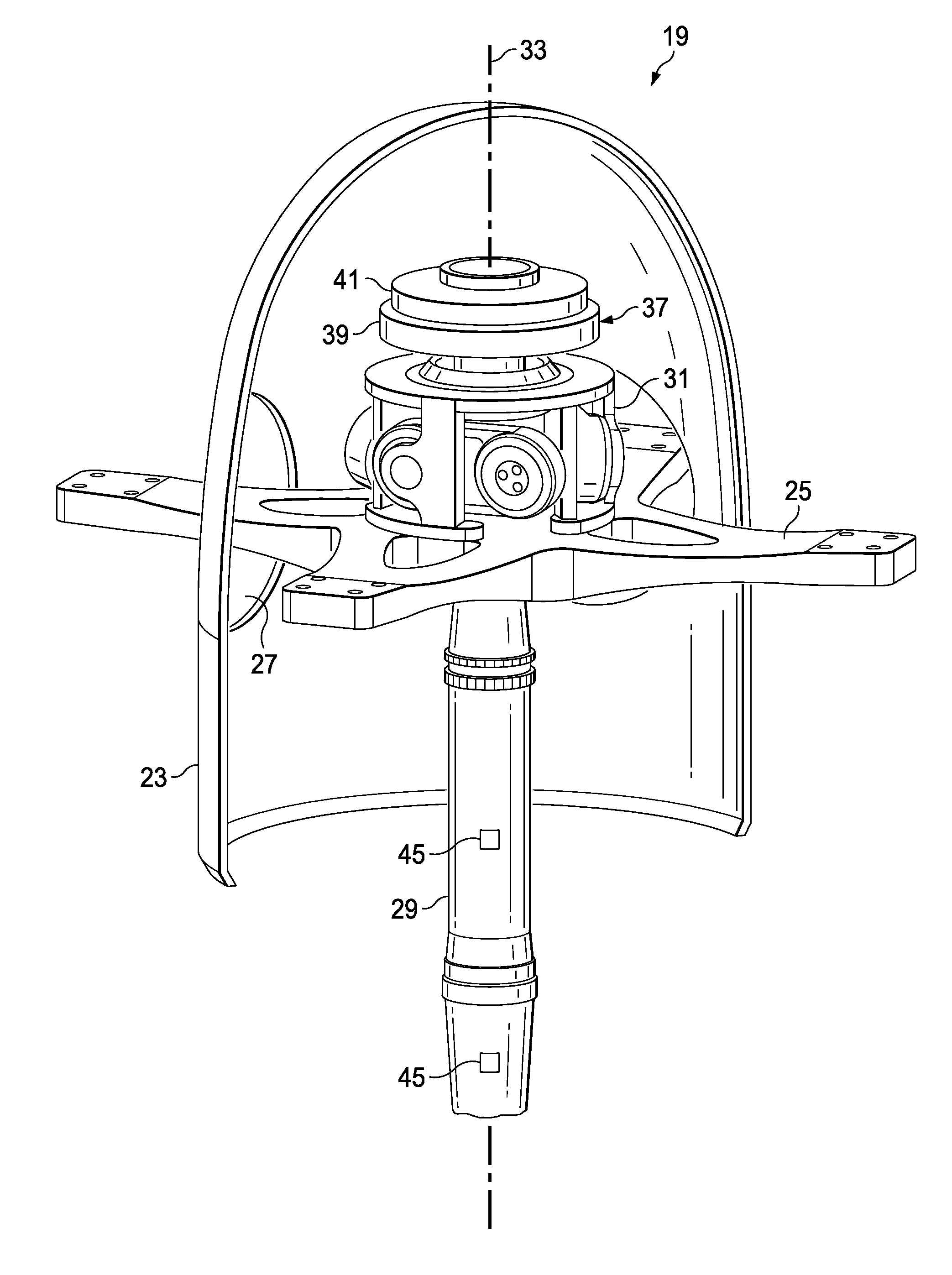
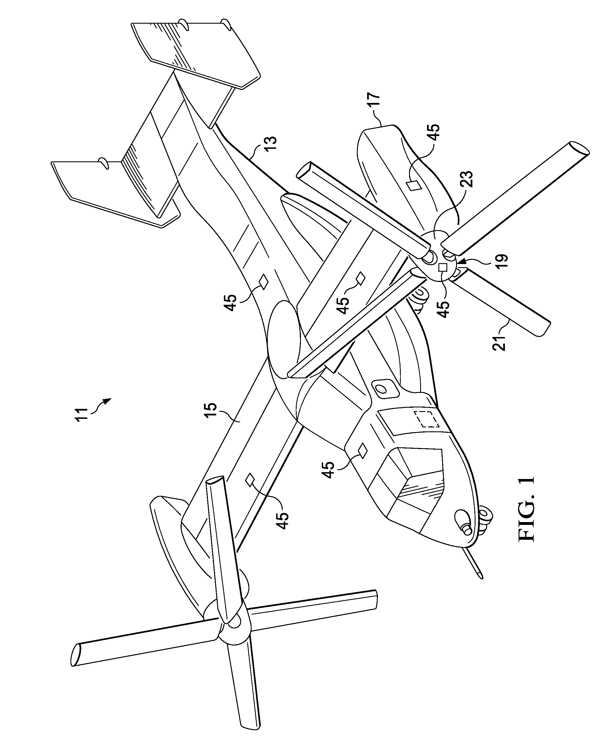
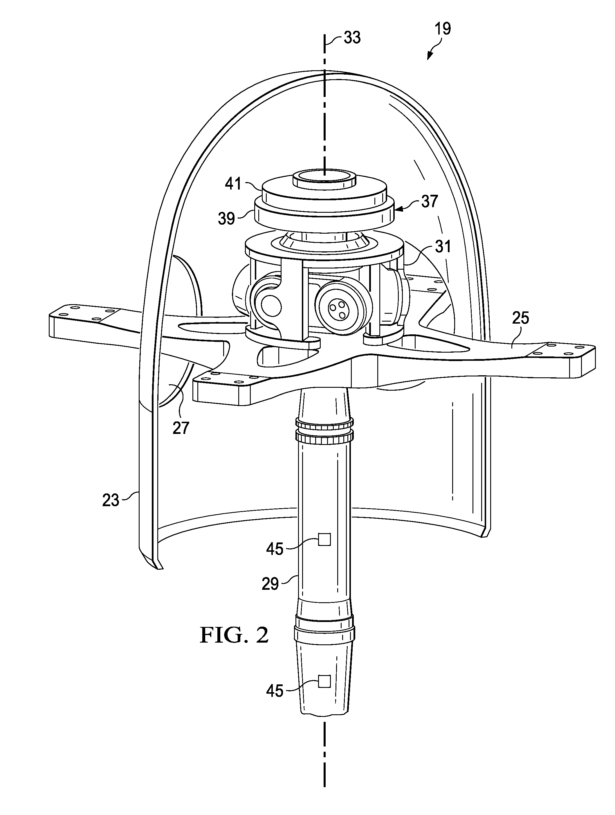
BACKGROUND[0001]1. Technical Field[0002]The present disclosure relates to vibration attenuation for rotor hubs.[0003]2. Description of Related Art[0004]Rotary-wing aircraft, such as helicopters and tiltrotors, have at least one rotor for providing lift and propulsion forces, and these rotors have at least two airfoil blades connected to a rotatable hub. The blades cause vibrations that are a function of the rotational speed of the rotor, and aircraft designers have difficulty accurately predicting the exact vibration modes that a particular rotor configuration will encounter. The vibrations can be transmitted through the rotor hub, through the rotor mast, through associated powertrain components, and into the airframe of the aircraft. The vibrations can reduce the life of affected components and cause undesirable vibration for passengers. Various types of vibration attenuation systems have been developed to reduce or eliminate these vibrations. The prior art includes both passive an...

Claims


Application Information

Patent Timeline
IPC IPC(8): B64C27/00
CPCB64C27/001B64C2027/005B64C2027/004B64C2027/003B64C29/0033
Inventor HEVERLY, II, DAVID E.DEWATERS, JEREMYSTAMPS, FRANK B.
Owner BELL HELICOPTER TEXTRON INC
Why Eureka
Try Eureka