Reflective Laminate Insulating Assembly

a technology of laminate insulating assembly and reflective laminate, which is applied in the direction of identification means, instruments, heating types, etc., can solve the problems of increasing thickness, reducing r value, and not providing sufficient insulation, so as to increase resistance to thermal flow and reduce insulation thickness

Active Publication Date: 2015-07-23
GRAY WILLIAM R
View PDF13 Cites 17 Cited by
  • Summary
  • Abstract
  • Description
  • Claims
  • Application Information

AI Technical Summary

Benefits of technology

[0009]The insulated HVAC duct component of the present system provides for increased resistance to thermal flow and can be constructed with reduced insulation thickness allowing insulation in smaller formats or installation of higher R value transition boxes in previously unavailable locations while meeting increasing municipal or industry standards for resistance to thermal flow.
[0011]The insulated HVAC duct component can include an adhesive intermediate the mineral wool layer and the reflective laminate layer. In one construction, the reflective laminate layer includes a base piece of reflective laminate material sized to overlap the bottom wall and two opposing sidewalls of the register box, and side pieces of reflective laminate material sized to overlap the other two opposing sidewalls to dispose the mineral wool intermediate the respective wall and the reflective laminate layer. The back wall of the register box can also include a circular inlet and a collar, wherein the base piece of reflective laminate material includes an aperture for receiving the collar. The mineral wool layer and the reflective laminate layer can be removably secured or retained within the register box by the lip.

Problems solved by technology

However, while the thickness of the insulation increases the R value, the increased thickness does not fit within a standard size transition box.
Although the insulation material can be compressed to fit inside the transition box, this reduces the R value and does not provide sufficient insulation.
While the size of the register box can be increased, this is costly, not aesthetically pleasing, and reduces available operable locations for the box.

Method used


Image

  • Reflective Laminate Insulating Assembly
  • Reflective Laminate Insulating Assembly
  • Reflective Laminate Insulating Assembly

Examples


Embodiment Construction

[0050]At the outset, it should be appreciated that the use of the same reference number throughout the several figures designates a like or similar element.

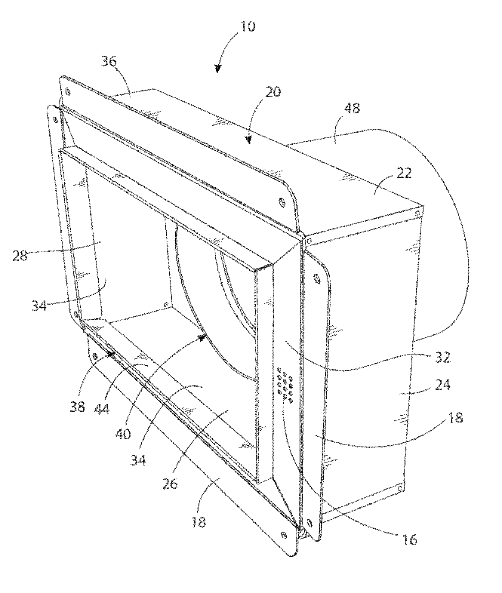
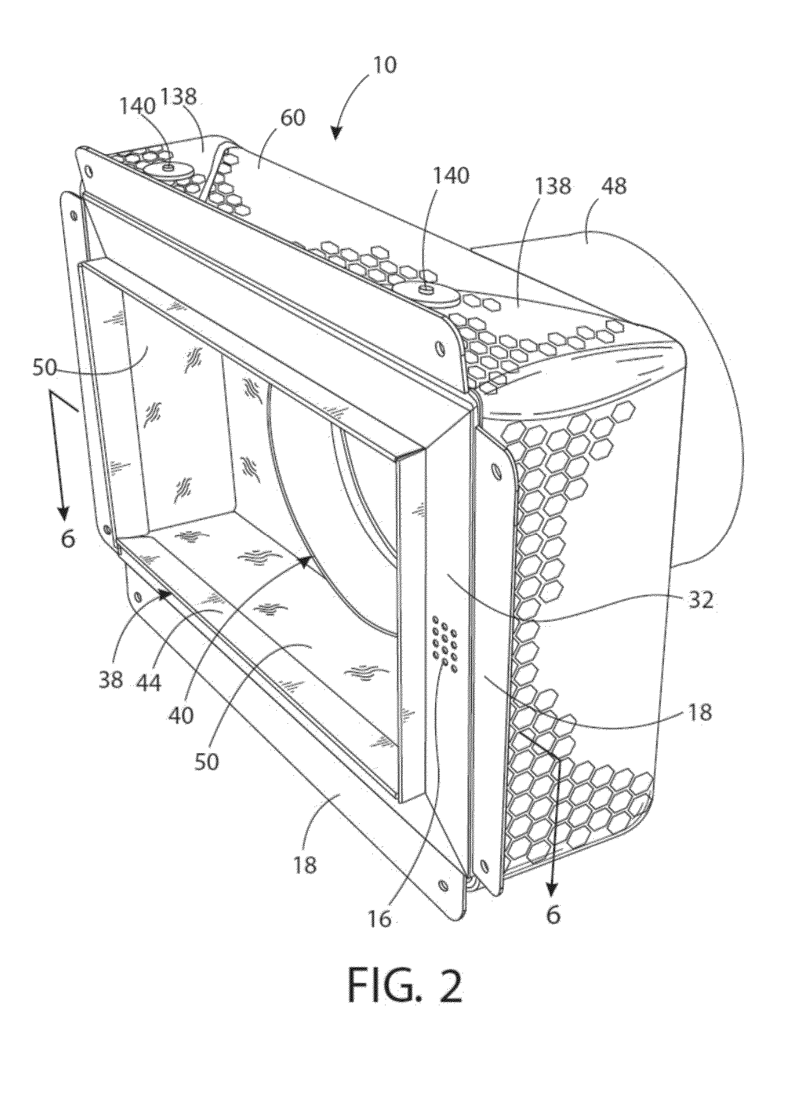
[0051]Referring to the Figures, an insulated HVAC duct component 10 includes an HVAC transition box 20, a mineral wool layer 50, and a reflective laminate layer 60. The HVAC transition box 20 (or transition box) includes fittings, collars, takeoffs, register boxes, boxes, boots, stacks, register boots, stackheads, reducers, elbows, caps and plenums. In one configuration, the transition box 20 includes sidewalls 22, 24, 26, 28, a back wall 30, and a front wall 32. The transition box 20 further includes an inside surface 34 and an outside surface 36, two access ports 38, 40 having different cross sections. In one configuration, the transition box 20 includes a rectangular access port 38 having a rectangular outlet framed by a depending rectangular lip 44 that is dimensioned for a snug sliding fit within the rectangular outlet. The ...


PUM

PropertyMeasurementUnit
thicknessaaaaaaaaaa
thicknessaaaaaaaaaa
densitiesaaaaaaaaaa

Abstract

An insulated HVAC duct component such as a transition box includes a first insulation layer and a second, different insulation layer. The transition box includes at least four sidewalls and one of a top and a back wall, the transition box further including a first access port and a second access port, the first access port having a different cross section than the second access port, one of the access ports being spaced from a nearest sidewall by less than 2 inches. The first insulation layer is located along an inside surface of the box. The second different insulation layer overlies the first insulation layer, the second different insulation layer having an air impervious surface, wherein the combined thickness of the first insulation layer and the second different insulation layer is less than 2 inches.

Description

CROSS-REFERENCE TO RELATED APPLICATIONS[0001]None.STATEMENT REGARDING FEDERALLY SPONSORED RESEARCH OR DEVELOPMENT[0002]None.REFERENCE TO A “SEQUENCE LISTING”[0003]None.BACKGROUND OF THE INVENTION[0004]1. Field of the Invention[0005]The present disclosure relates to insulated HVAC duct components and more specifically to after market pre-formed insulating components and insulated HVAC transition boxes having a first insulation layer and a second, different insulation layer.[0006]2. Description of the Related Art[0007]The insulation of ducts, such as HVAC ducts, provides a number of benefits including energy efficiency and noise reduction. Typically, mineral wool insulation is placed inside or outside duct components to provide such benefits. Recent changes in building codes and regulations, however, now require that transition boxes, including register boxes, have increased R values. To increase the R value of and resist thermal transfer in HVAC systems, an increased amount of minera...

Claims


Application Information

Patent Timeline
Patent Type & Authority Applications(United States)
IPC IPC(8): F24F13/02
CPCF24F13/0263F24F13/0272F24F13/0281F24F13/0245Y10T29/49796Y10T428/15Y10T428/24826Y10T428/249953B32B37/12B32B37/14B32B2307/416B32B2509/00F24F13/24
Inventor GRAY, WILLIAM R.
Owner GRAY WILLIAM R
Why Eureka
Try Eureka