Device and method for monitoring an electrical network

Active Publication Date: 2015-07-23
KLONOWSKI THOMAS +1
View PDF4 Cites 16 Cited by
  • Summary
  • Abstract
  • Description
  • Claims
  • Application Information

AI Technical Summary

Problems solved by technology

However, conventional means are only very ineffective against faults and the initial signs thereof, which are surreptitious, non-stationary and very low-energy in nature.
However, due to the difficulty in detecting these faults belonging to the electrical discharge category (for example, initial signs of the start of an electric arc, Trichel pulse, brush discharges, etc.) may damage the wiring of the electrical network.
Faults due to electrical discharges are generally well-known but are still poorly detected to date and the consequences thereof poorly diagnosed.

Method used


Image

  • Device and method for monitoring an electrical network
  • Device and method for monitoring an electrical network
  • Device and method for monitoring an electrical network

Examples


Embodiment Construction

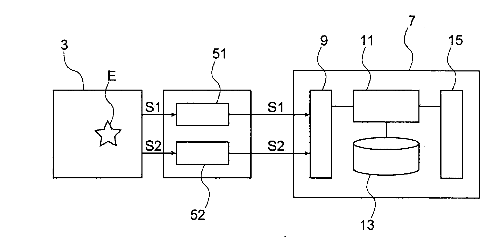
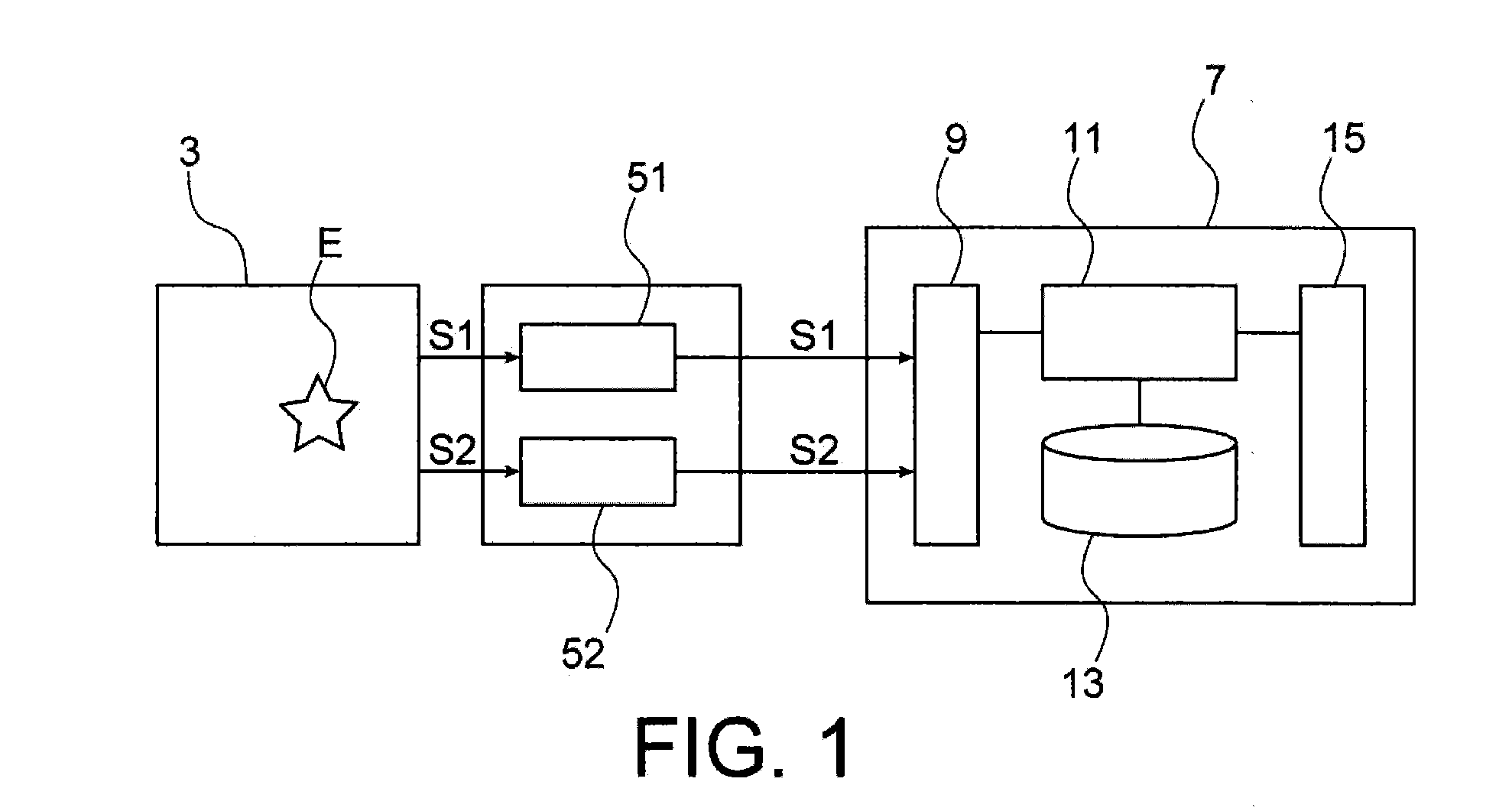
[0012]The present invention is defined by a device for monitoring an electrical network, comprising:[0013]means for detecting electrical signals and additional signals produced in the electrical network, the additional signals being of a different physical nature to the electrical signals,[0014]means for processing said electrical signals to define a first time reference representing a detection time of the electrical signals emitted upon a fault event arising in the electrical network,[0015]means for processing said additional signals to define a second time reference representing a detection time of the additional signals emitted upon said fault event arising in the electrical network, and[0016]processing means for spatially locating said fault event in the electrical network according to said first and second time references.

[0017]In this way, the device according to the invention simply implements, without injecting signals into the electrical network, non-intrusive detection of...


PUM


Abstract

A method and device for monitoring an electrical network, including: a mechanism detecting electrical signals and additional signals produced in the electrical network, the additional signals being of a different physical nature to the electrical signals; a mechanism for processing the electrical signals to define a first time reference representing a detection time of the electrical signals emitted upon a fault event arising in the electrical network; a mechanism processing the additional signals to define a second time reference representing a detection time of the additional signals emitted upon the fault event arising in the electrical network; and a processor spatially locating the fault event in the electrical network according to the first and second time references.

Description

FIELD OF THE INVENTION[0001]The present invention relates to a method and device for monitoring an electrical network for detecting faults or initial signs of failure in an electrical network.STATE OF THE RELATED ART[0002]An electrical network is used to carry electrical energy at different electrical loads and comprises conventional protection means in respect of short-circuits, overcurrents or other faults.[0003]Conventional protection means make it possible to prevent complete degradation of the network and are effective when the faults are high-energy such as short-circuits, continuous and progressive such as overloads, one-off but with significant variations in current and voltage, or recurrent over time.[0004]However, conventional means are only very ineffective against faults and the initial signs thereof, which are surreptitious, non-stationary and very low-energy in nature.[0005]However, due to the difficulty in detecting these faults belonging to the electrical discharge c...

Claims


Application Information

Patent Timeline
IPC IPC(8): G01R31/08
CPCG01R31/088G01R31/086G01R31/14Y04S10/52G01R31/08
Inventor KLONOWSKI, THOMASYBANEZ, LUDOVIC
Owner KLONOWSKI THOMAS
Why Eureka
Try Eureka