Method for angle estimation and radar sensor for motor vehicles

a technology for motor vehicles and angle estimation, applied in the direction of antenna adaptation in movable bodies, instruments, measurement devices, etc., can solve the problems of inability to accurately estimate angle, and inability to use multiple dimensions at the same time. achieve the effect of simple and more accurate angle estimation

Active Publication Date: 2015-07-23
ROBERT BOSCH GMBH
View PDF5 Cites 51 Cited by
  • Summary
  • Abstract
  • Description
  • Claims
  • Application Information

AI Technical Summary

Benefits of technology

[0009]An object of the invention is to describe a method that enables simpler and more accurate angle estimation in situations in which reflections of the radar signal from elongated objects are to be expected.
[0013]Limiting the search space results in a considerable reduction in calculation outlay. It is moreover apparent that the accuracy of the angle estimate is also improved by this method.

Problems solved by technology

If the distances and relative speeds of the two targets are so similar to one that a separation is not possible given the limited resolution of the radar sensor, however, the two targets then appear as a single target, and the above-described angle estimate would yield only a single angle as a result.
But because there are in fact two targets, interference occurs between the signals that are backscattered from the two targets and become superimposed at the radar sensor.
Multi-target estimation has the disadvantage, however, that searching in a multi-dimensional search space is extremely calculation-intensive.
The method is moreover susceptible to errors due to the unavoidable signal noise.
Although the signal reflected from the road surface or guardrail takes a certain detour, it is hardly measurable given the almost raking reflection.

Method used


Image

  • Method for angle estimation and radar sensor for motor vehicles
  • Method for angle estimation and radar sensor for motor vehicles
  • Method for angle estimation and radar sensor for motor vehicles

Examples


Embodiment Construction

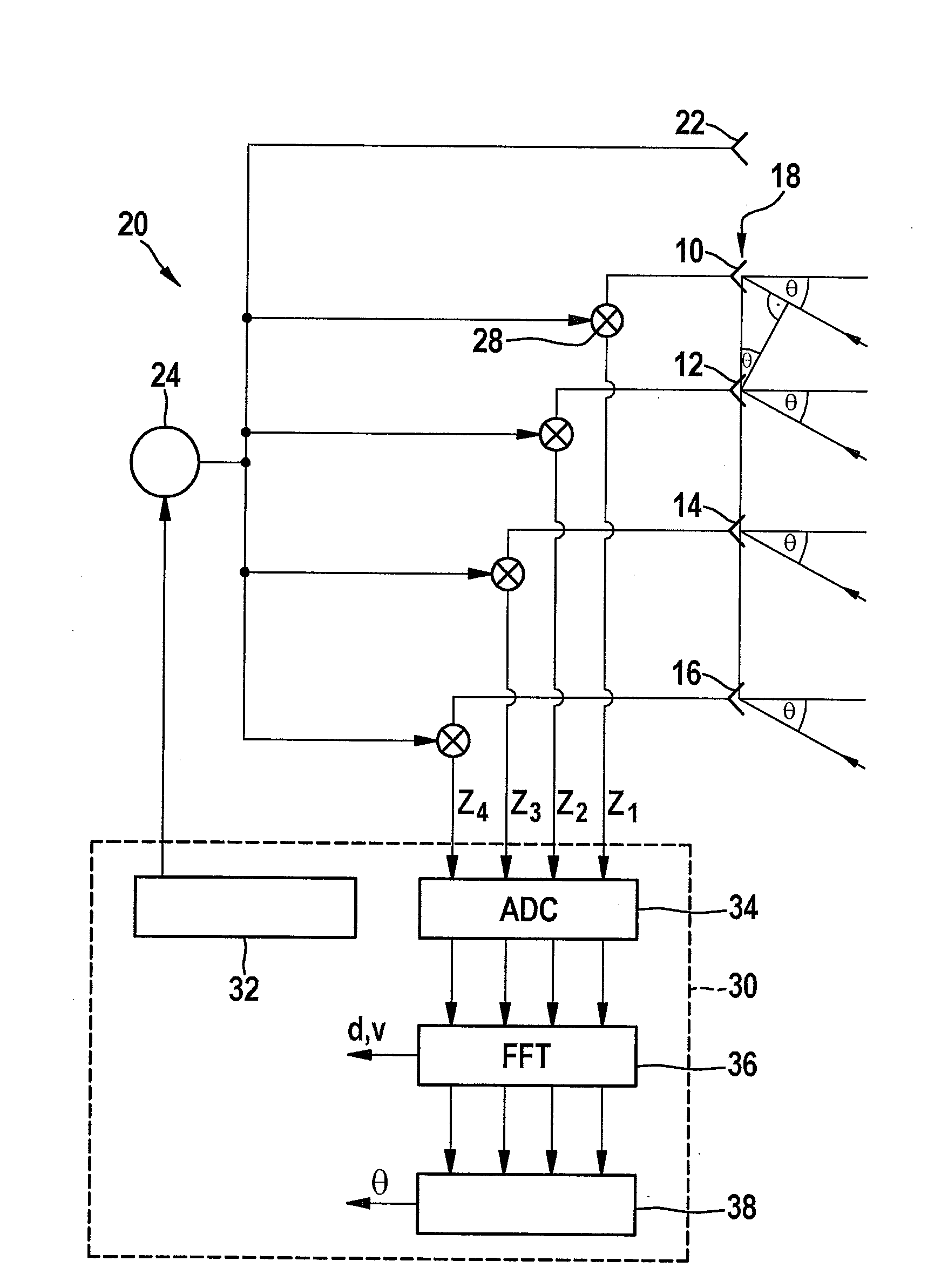
[0022]The radar sensor shown in FIG. 1 has four receiving antenna elements 10, 12, 14, 16 that together form a planar group antenna 18. The radar sensor is incorporated into a motor vehicle in such a way that antenna elements 10 to 16 are located next to one another at the same height, so an angular resolution capability of the radar sensor in the horizontal (in azimuth) is achieved. FIG. 1 symbolically depicts radar beams that are received by the antenna elements at an azimuth angle θ.

[0023]A high-frequency section 20 for applying control to a transmitting antenna element 22 is constituted, for example, by a monolithic microwave integrated circuit (MMIC), and encompasses a local oscillator 24 that generates the radar signal to be transmitted. The radar echoes received by antenna elements 10 to 16 are respectively delivered to a mixer 28, where they are mixed with the transmitted signal supplied by oscillator 24. This yields, for each of the antenna elements, an intermediate-frequen...


PUM


Abstract

A method for a radar sensor for a motor vehicle, for angle estimation of radar targets based on an antenna diagram that indicates, for various configurations of radar targets, pertinent amplitudes and / or phase correlations between signals which are obtained for the relevant configuration in multiple evaluation channels of the radar sensor, wherein for a single real target, the occurrence of a number n of apparent targets, which are caused by reflection of the signal coming from the real target from elongated objects, is modeled mathematically; a correlation between the location angle of the real target and the location angles of the apparent targets is calculated; and to estimate the location angle of the real target, a multi-target estimate is performed in an n-dimensional search space and the search is limited to a sub-space that is determined by the calculated correlation.

Description

RELATED APPLICATION INFORMATION[0001]The present application claims priority to and the benefit of German patent application no. 10 2014 201 026.8, which was filed in Germany on Jan. 21, 2014, the disclosure of which is incorporated herein by reference.FIELD OF THE INVENTION[0002]The present invention relates to a method for a radar sensor for motor vehicles, for angle estimation of radar targets based on an antenna diagram that indicates, for various configurations of radar targets, pertinent amplitudes and / or phase correlations between signals which are obtained for the relevant configuration in multiple evaluation channels of the radar sensor; and to a radar sensor for executing said method.BACKGROUND INFORMATION[0003]Radar sensors are used in motor vehicles, for example, in order to measure the distances, relative speeds, and azimuth angles of vehicles or other objects located in the area in front of the own vehicle. Multiple antenna elements are then disposed, for example, at a...

Claims


Application Information

Patent Timeline
Patent Type & Authority Applications(United States)
IPC IPC(8): G01S13/42H01Q1/32G01S13/931
CPCH01Q1/32G01S13/42G01S7/41G01S13/34G01S13/931
Inventor KUEHNLE, GOETZGROSS, VOLKERLOESCH, BENEDIKT
Owner ROBERT BOSCH GMBH
Why Eureka
Try Eureka