Optical data processing device, optical data processing system, optical data processing method, and optical data processing program

a technology of optical data processing and optical data, applied in the field of optical data processing techniques, can solve the problems of inability to obtain point cloud position data of a part, occlusion generated by flickering images of passersby, and inability to obtain it, and achieve the effect of high precision

Active Publication Date: 2015-07-23
KK TOPCON
View PDF2 Cites 83 Cited by
  • Summary
  • Abstract
  • Description
  • Claims
  • Application Information

AI Technical Summary

Benefits of technology

[0011]According to the first aspect, multiple three-dimensional edges that extend in the specific direction in each of two three-dimensional models are focused on, the similarity between two three-dimensional models is obtained, and three-dimensional edges which correspond between both models are selected based on this similarity. When the three-dimensional edges are handled, an amount of data to be handled is less than that in the case in which a point cloud itself is handled, and the three-dimensional edge is easily understood (in other words, it is easily distinguished from other parts). Therefore, a processing for specifying a correspondence relationship between both of the three-dimensional models can be carried out with high precision and extremely efficiently.
[0027]According to the present invention, processing for specifying a correspondence relationship of feature points between two sets of optical data can be carried out with high precision and extremely efficiently.

Problems solved by technology

In the case in which the point cloud position data is obtained from one viewpoint, point cloud position data of a part in which a shadow is formed by a shape of the object to be measured or an obstruction when it is viewed from the viewpoint, cannot be obtained.
There is a problem in which occlusion is generated by flickering images of passersby, passing vehicles, trees, etc.
This processing is complicated, and required processing time is long.
However, in this technique, it is necessary to adhere the targets to the object to be measured, and for example, the targets cannot be simply adhered when the object to be measured is a tall building, etc.
However, there are problems in that a matching error is large, a required processing time is too long, and a large burden is applied to a calculating device.

Method used


Image

  • Optical data processing device, optical data processing system, optical data processing method, and optical data processing program
  • Optical data processing device, optical data processing system, optical data processing method, and optical data processing program
  • Optical data processing device, optical data processing system, optical data processing method, and optical data processing program

Examples


first embodiment

1. First Embodiment

Assumption

[0043]The main objects to be measured in the present embodiment are buildings.

DEFINITION OF TERMS

[0044]In the following, the terms used in the specification will be explained.

Labels

[0045]The labels are identifiers for specifying a plane (or for distinguishing from other planes). The plane is a suitable plane for selecting as an object to be calculated, and it includes a flat surface, a curved surface having large curvature, and a curved surface having large curvature and small change at a curved position. In this specification, the plane and a non-plane are distinguished based on an allowable calculating amount that is mathematically understood (obtained from data) by calculation. The non-plane includes a corner, an edge part, a part having small curvature, and a part having large change at a curved portion. In these parts, a large amount of the mathematically understood (obtained from data) calculation is required, and burden on a calculation device and...

second embodiment

2. Second Embodiment

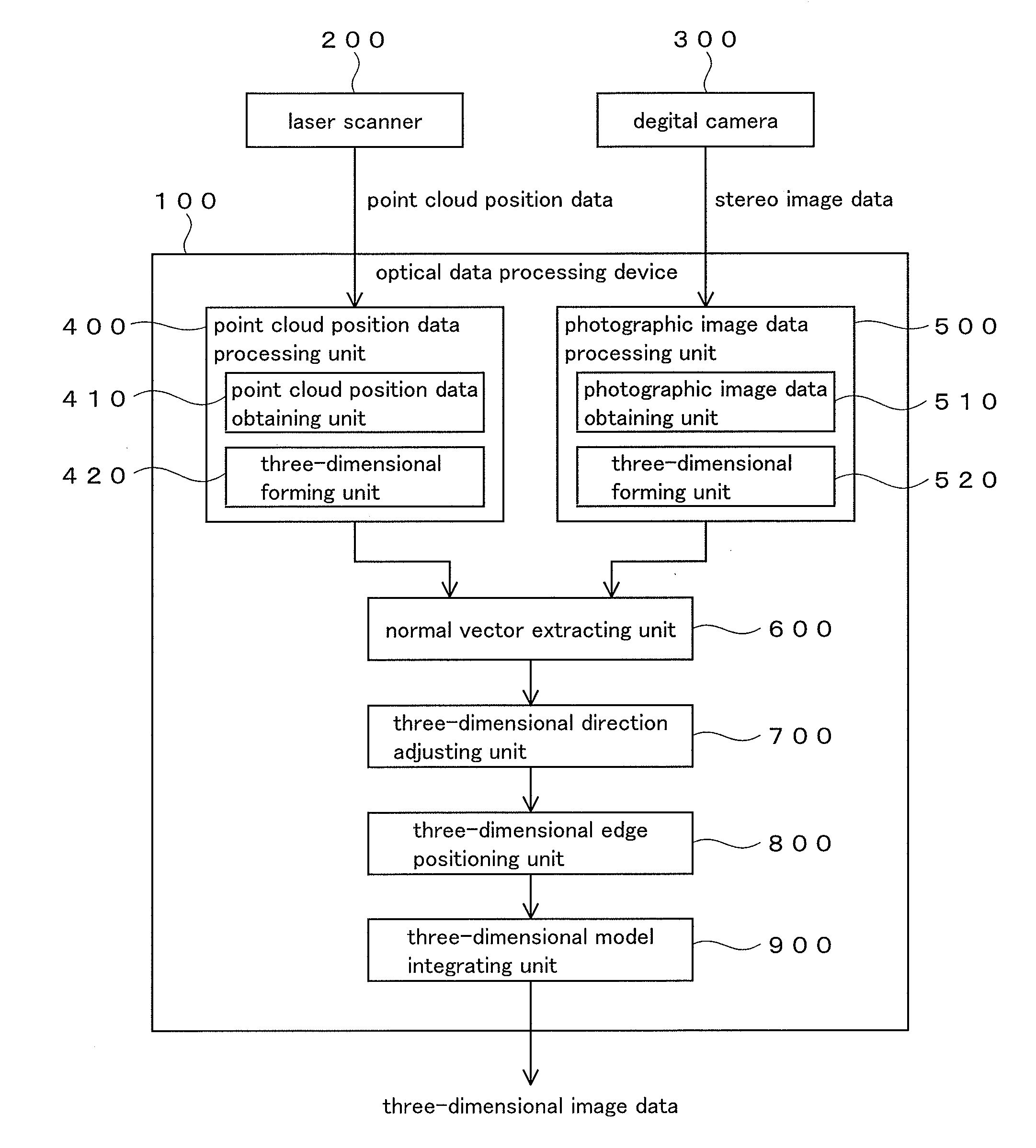
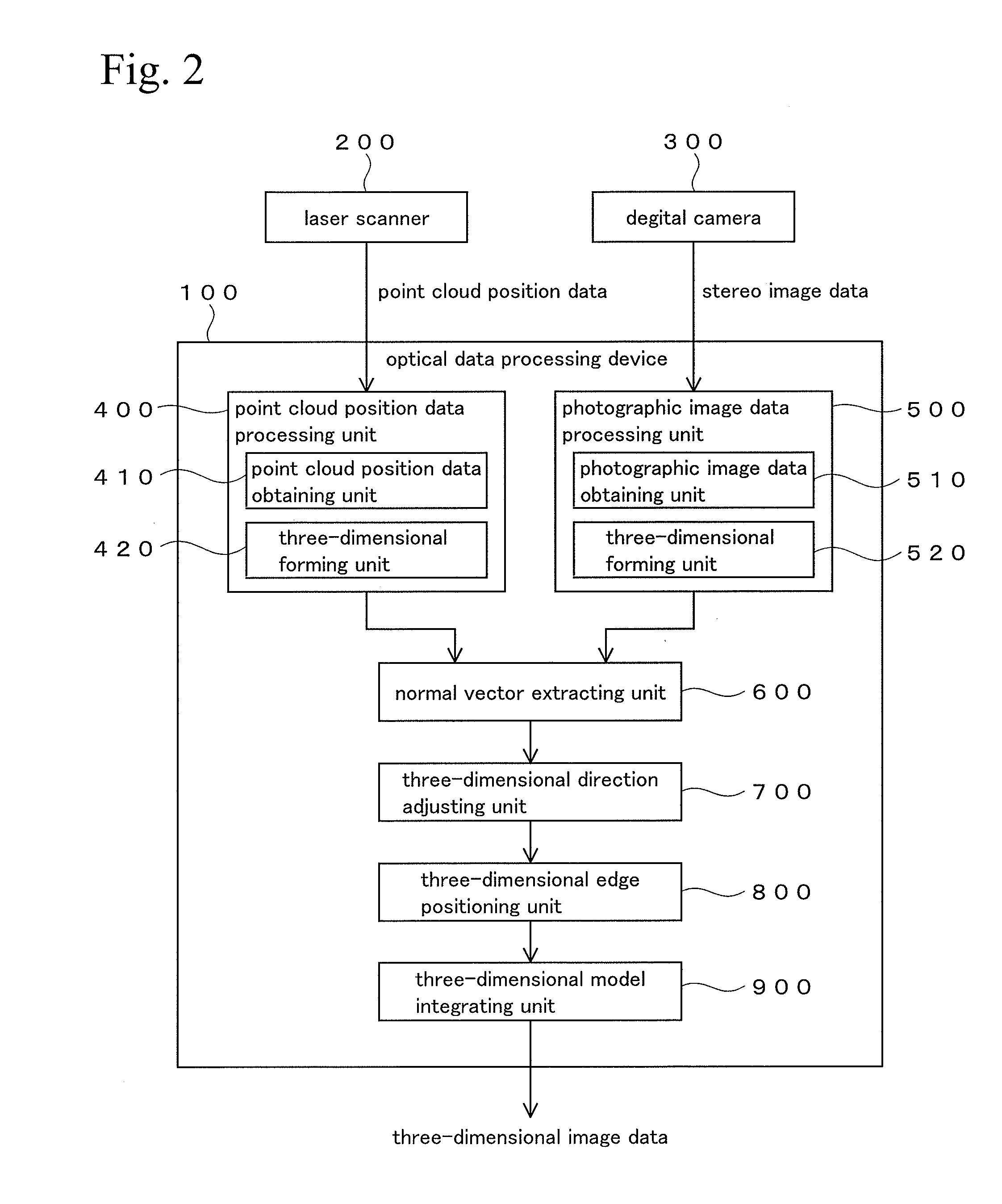
[0151]In the first embodiment, the case in which a main three-dimensional model is a laser point cloud three-dimensional model and an image measuring three-dimensional model is used in order to compensate for a part in which occlusion is generated in the laser point cloud three-dimensional model, was explained. Conversely, the image measuring three-dimensional model may be a main three-dimensional model and the laser point cloud three-dimensional model may be used for compensating in the main model. In this case, a procedure of the processing is the same as that of the First Embodiment. It is difficult for an object range of the image measuring three-dimensional model to be wider and a part of the range (including a part in which the occlusion is generated, a part having low accuracy, etc.) is compensated for by the laser point cloud three-dimensional model.

[0152]In this case, the image measuring three-dimensional model may not have an actual scale as described i...

third embodiment

3. Third Embodiment

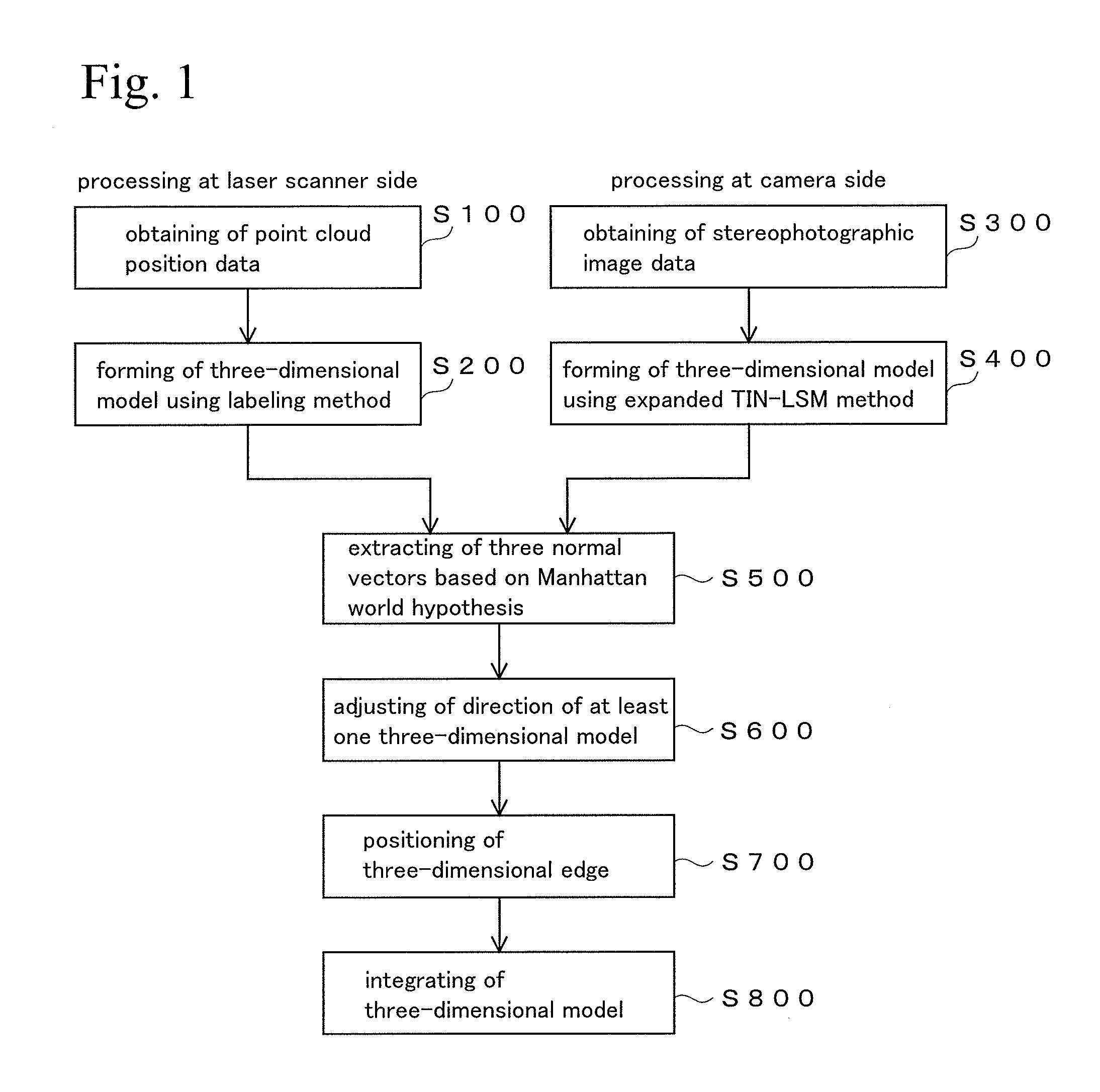
[0154]Both of two three-dimensional models to be integrated may be laser point cloud three-dimensional models. In this case, the laser scanning is carried out from each of different viewpoints, a first laser point cloud three-dimensional model and a second laser point cloud three-dimensional model are obtained, and these two three-dimensional models are integrated by the procedure shown in the First Embodiment. Here, positioning in Step S700 in FIG. 1 is carried out by a rigid body conversion (including slight direction compensation) or parallel translation, which is not an affine transformation, with respect to one or both of the three-dimensional models, since the two three-dimensional models are absolute models in which coordinate values of the point cloud position are found. Therefore, in the case of this example, a part denoted by a reference numeral 805 in FIG. 12 functions as a rigid body conversion processing unit or a parallel translation processing unit ...


PUM


Abstract

A processing for specifying a correspondence relationship of feature points between two sets of optical data can be highly precise and efficiently carried out. The correspondence relationship of the perpendicular edges is obtained based on the assumption that the object is a building, in the processing for integrating the three-dimensional model obtained from the point cloud position data and the three-dimensional model obtained from the stereophotographic image. In this case, one perpendicular edge is defined by the relative position relationship with the other perpendicular edge, and the correspondence relationship is high-precisely and rapidly searched.

Description

BACKGROUND OF THE INVENTION[0001]1. Technical Field[0002]The present invention relates to an optical data processing technique, and specifically relates to a technique for integrally processing three-dimensional data obtained from different points of view.[0003]2. Background Art[0004]A technique in which a three-dimensional position of an object to be measured is obtained as a large number of point cloud position data by irradiating a laser beam onto object to be measured while scanning, and a three-dimensional shape of the object to be measured is calculated by this point cloud position data, has been known (see Patent Document 1). In the point cloud position data, a two-dimensional image and three-dimensional coordinates are combined. That is, in the point cloud position data, data of a two-dimensional image of an object, multiple measured points (point cloud) corresponding to this two-dimensional image, and position in three-dimensional space (three-dimensional coordinates) of th...

Claims


Application Information

Patent Timeline
Patent Type & Authority Applications(United States)
IPC IPC(8): G06K9/46G06T3/40G06T17/00G06T15/20G06K9/62G06V10/44
CPCG06K9/4604G06T15/20G06T3/403G06T17/00G06K9/6215G01B11/00G06T17/05G06T17/10G06T2210/56G06T7/593G06V10/44G06F18/22
Inventor KOCHI, NOBUOKITAMURA, KAZUO
Owner KK TOPCON
Why Eureka
Try Eureka