Core manufacturing device and core manufacturing method

Inactive Publication Date: 2015-07-23
JTEKT CORP
View PDF2 Cites 12 Cited by
  • Summary
  • Abstract
  • Description
  • Claims
  • Application Information

AI Technical Summary

Benefits of technology

[0013]An object of the present invention is to provide a core manufacturing device and a core manufacturing method ca

Problems solved by technology

In the case where the magnetization process is performed with the rotor core maintained at a high temperature, however, the permanent magnets of the rotor core may be irreversibly demagnetized depending on the timing to detach the rotor core from the magnetization device.
In the case where such a method is used, however, the magnetization device cannot be used wh

Method used


Image

  • Core manufacturing device and core manufacturing method
  • Core manufacturing device and core manufacturing method
  • Core manufacturing device and core manufacturing method

Examples


first embodiment

[0039]a manufacturing device and a manufacturing method for a rotor core will be described. First, the structure of the rotor core is described. The rotor core according to the embodiment is a so-called inner rotor used in a synchronous motor and disposed inside a cylindrical stator.

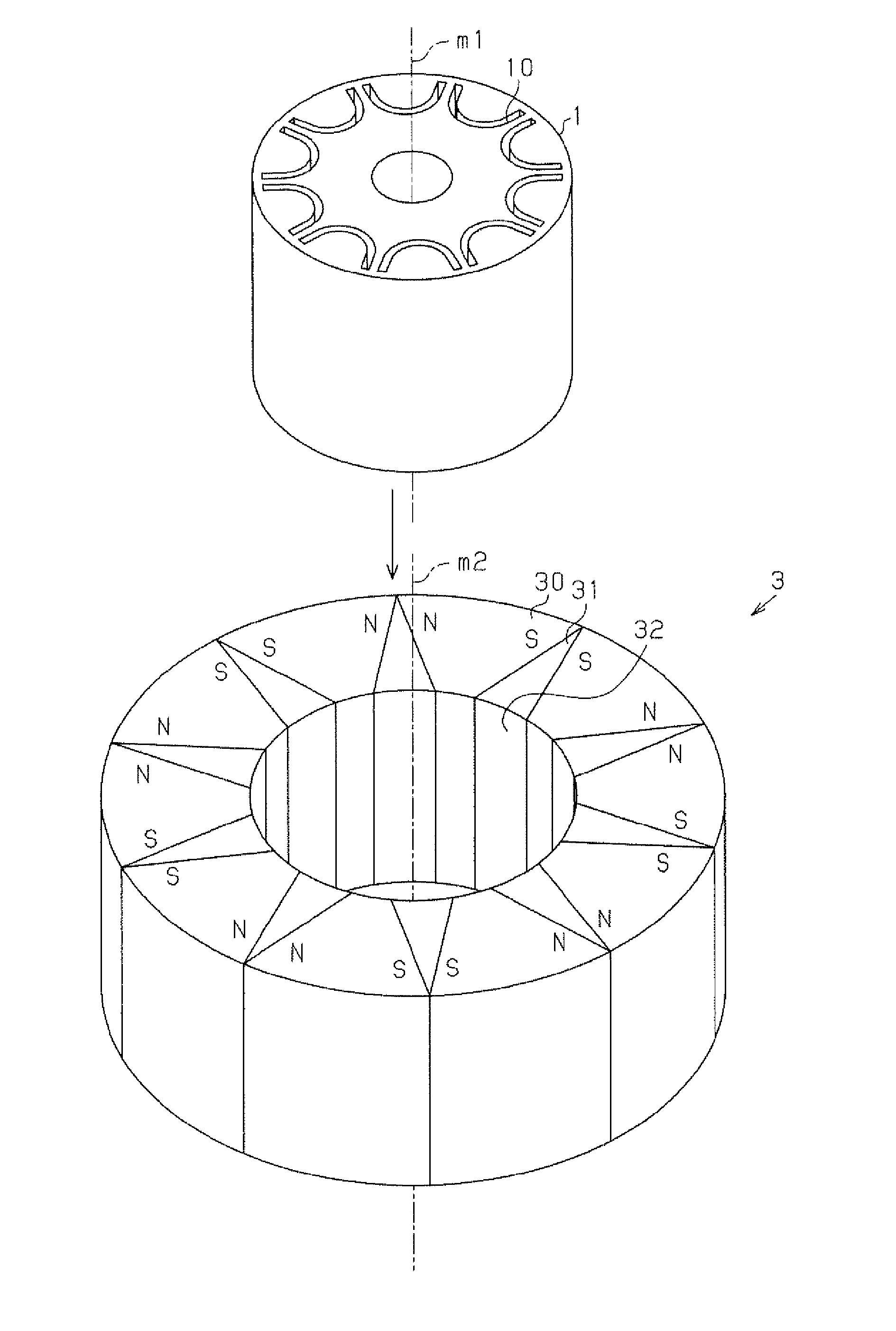
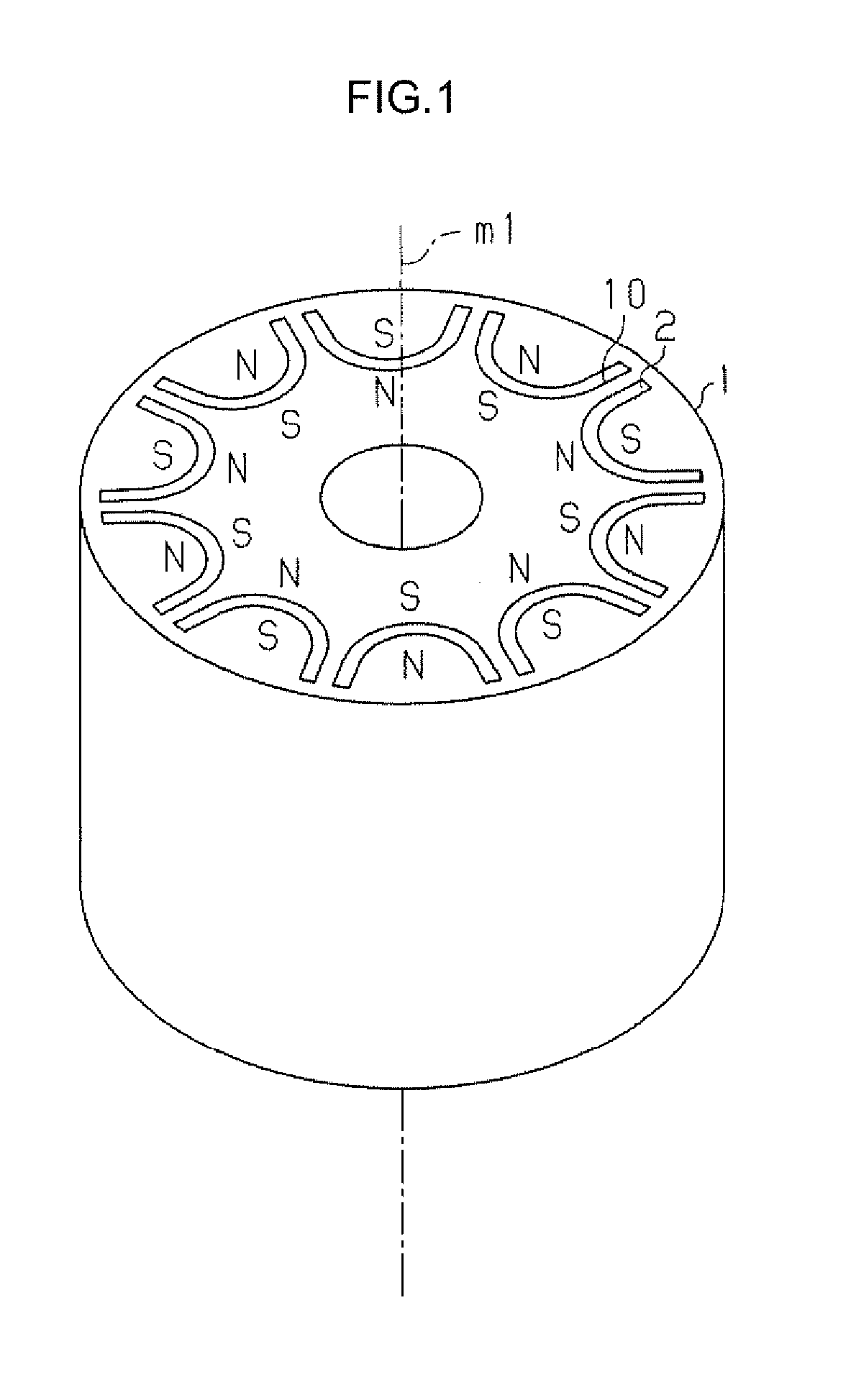
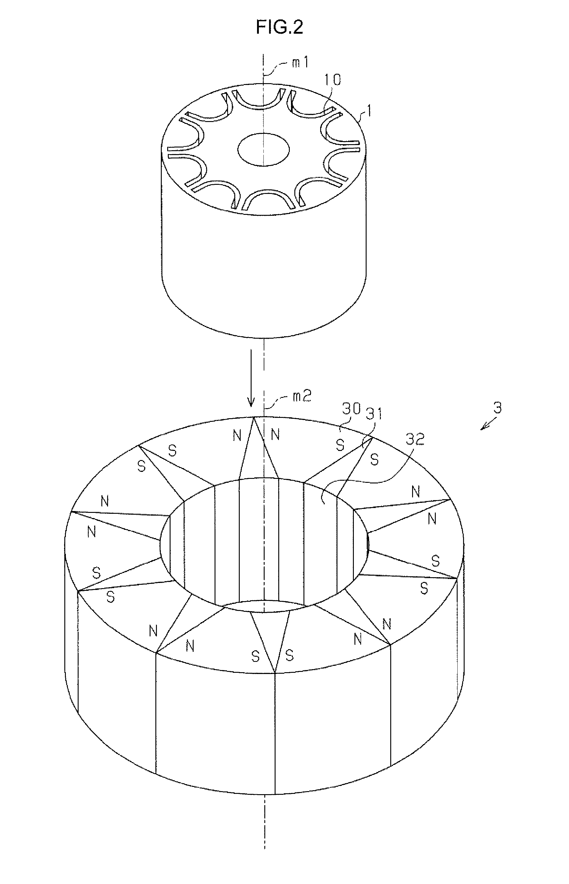
[0040]As illustrated in FIG. 1, a rotor core 1 is formed in a cylindrical shape around an axis m1. The rotor core 1 is structured by stacking a plurality of electromagnetic steel sheets in the axial direction. A plurality of magnet insertion holes 10 are formed at equiangular intervals in the circumferential direction to penetrate the rotor core 1 in the axial direction. The magnet insertion holes 10 have a U shape that opens toward the outer peripheral side of the rotor core in cross section taken along a plane that is orthogonal to the axial direction of the rotor core. Permanent magnets 2 are disposed in the magnet insertion holes 10. The permanent magnets 2 are composed of bond magnets such as neodym...

second embodiment

[0065]As illustrated in FIG. 16, a plurality of void portions 70 are formed at equiangular intervals in the circumferential direction to penetrate the jig 7 according to the embodiment in the axial direction. It should be noted, however, that the embodiment is different from the second embodiment in that the magnetic barrier members 71 are not embedded in the void portions 70. In the following description, the jig 7 will be referred to as a first jig for convenience.

[0066]In the embodiment, in addition, a second jig 9 that is separate from the first jig 7 is used. The second jig 9 is composed of a soft magnetic body, and has an annular portion 90 and a plurality of cylindrical pins 91 formed at equiangular intervals on an end surface of the annular portion 90 in the axial direction. The outside diameter of the pins 91 is set to be generally equal to the inside diameter of the void portions 70 of the first jig 7. The length of the pins 91 in the axial direction is set to be generally...


PUM

PropertyMeasurementUnit
Diameteraaaaaaaaaa
Permeabilityaaaaaaaaaa
Magnetismaaaaaaaaaa

Abstract

A manufacturing device for a rotor core includes: a magnetization device that magnetizes magnet raw materials before being magnetized disposed in magnet insertion holes of the rotor core to turn the magnet raw materials before being magnetized into permanent magnets; and a detachment device that detaches the rotor core from the magnetization device. The detachment device also functions as a mounting device that mounts a jig around the rotor core when the rotor core is detached from the magnetization device.

Description

INCORPORATION BY REFERENCE[0001]The disclosure of Japanese Patent Application No. 2014-008533 filed on Jan. 21, 2014 including the specification, drawings and abstract, is incorporated herein by reference in its entirety.BACKGROUND OF THE INVENTION[0002]1. Field of the Invention[0003]The present invention relates to a core manufacturing device and a core manufacturing method.[0004]2. Description of Related Art[0005]There have been known Interior Permanent Magnet (IPM) motors in which permanent magnets for field excitation are embedded inside a rotor. Japanese Patent No. 4726105 describes an example of a manufacturing method for a rotor core for use in the IPM motors. In the manufacturing method described in Japanese Patent No. 4726105, first, a cylindrical rotor core in which a plurality of magnet insertion holes are formed is shaped, and thereafter magnet raw materials before being magnetized are injected into the magnet insertion holes through injection molding. After that, a magn...

Claims


Application Information

Patent Timeline
IPC IPC(8): H01F13/00
CPCH01F13/003H02K15/03Y10T29/49012Y10T29/53143
Inventor NIMURA, KEITAKANDA, NAOTAKEYAMAGUCHI, RYOSUKE
Owner JTEKT CORP
Why Eureka
Try Eureka