Bus bar and motor comprising same

a technology of bus bars and motors, applied in the direction of washers, coupling devices, mechanical equipment, etc., can solve the problems of inability to manufacture housings with a large size and complicated shapes, weak housings to radial force, and deformation of housings, etc., to achieve the effect of ensuring assembly process productivity, constant coupling force, and complicated housing structur

Active Publication Date: 2022-06-07
LG INNOTEK CO LTD
View PDF26 Cites 0 Cited by
  • Summary
  • Abstract
  • Description
  • Claims
  • Application Information

AI Technical Summary

Benefits of technology

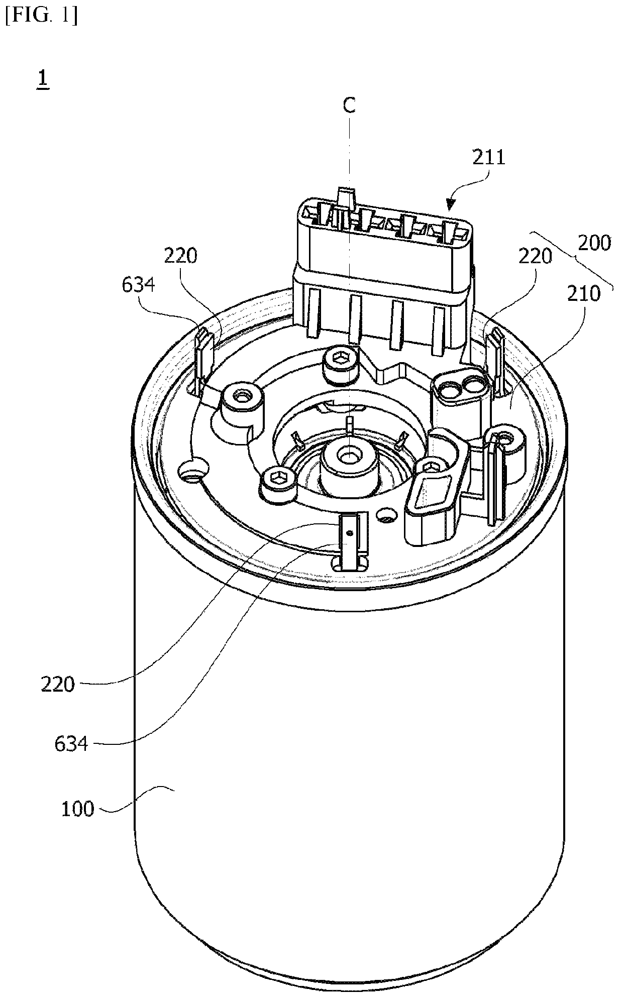
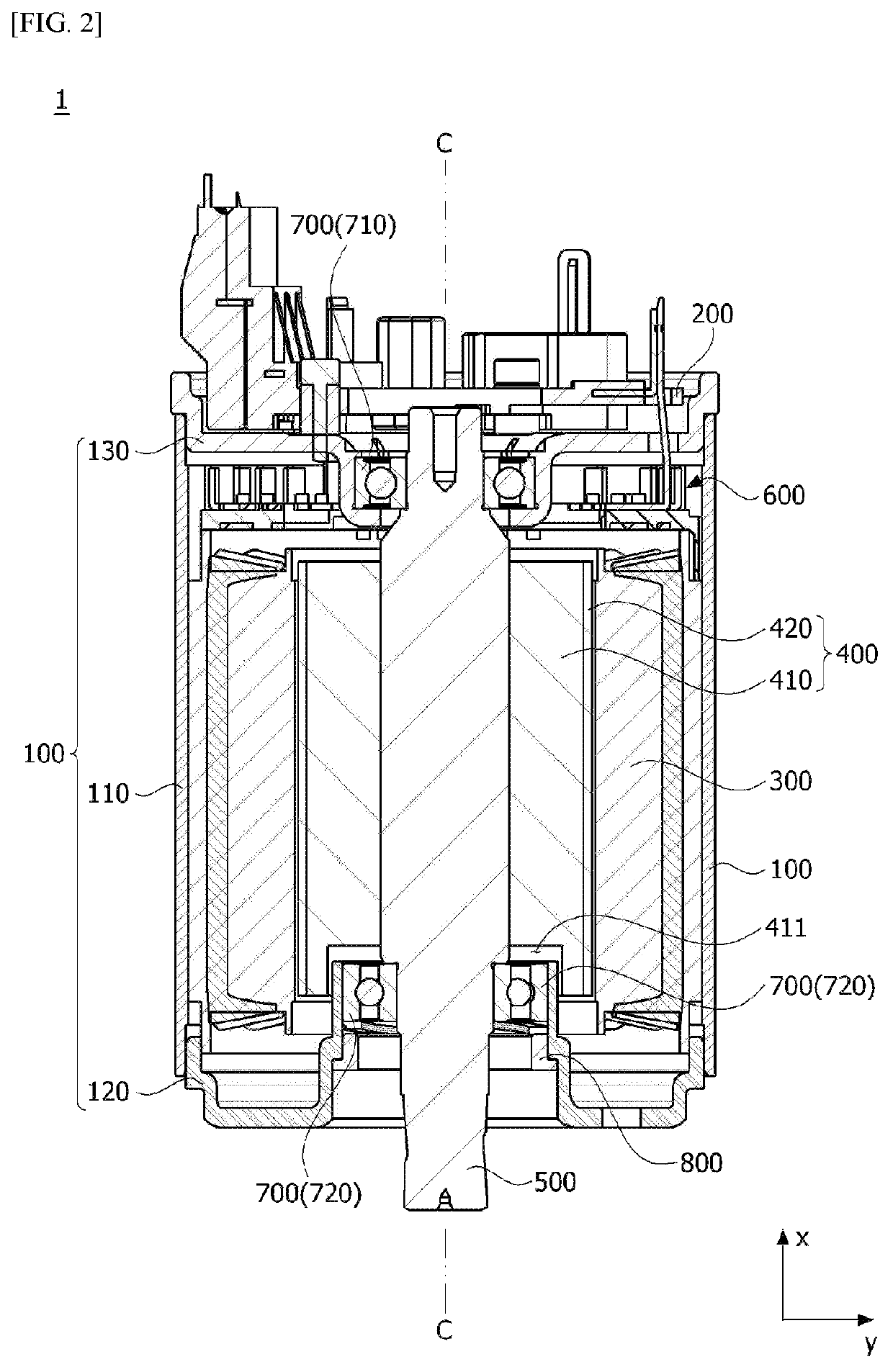
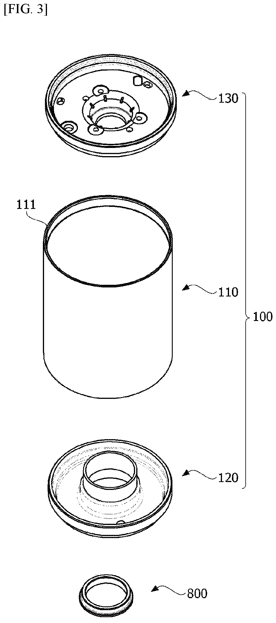
[0048]In a motor according to embodiments, since a housing includes a housing body having a pipe shape, a first flange, and a second flange, a productivity of an assembly process can be secured, and a complicated structure of the housing can be realized.
[0049]In addition, since the housing body is coupled to the first flange and the second flange using a press fit method, a constant coupling force can be secured when compared to a coupling method using a conventional caulking process.
[0050]In a bus bar according to the embodiments and the motor including the same, since a two-layer structure in which a plurality of terminals are disposed on each of an upper surface and a lower surface of a bus bar body is realized, space utilization can be improved.
[0051]In addition, since terminals are disposed so as not to deviate from an outer circumferential surface of the bus bar body in a radial direction of the bus bar, horizontal space utilization can be improved.
[0052]In addition, since shapes of the terminals are simplified, and some parts of the terminals are unified, a terminal manufacturing cost can be reduced.
[0054]In addition, the terminals can be coupled to a main body of the bus bar through heat fusing without using an additional coupling member.

Problems solved by technology

However, since the deep drawing method enables a product having a small size and a simple shape to be produced, there is a problem in that it cannot be used to manufacture a housing having a large size and a complicated shape.
In addition, in the case of the housing manufactured using the deep drawing method, there is a problem in that the housing is weak to a force applied in a radial direction.
For example, in a case in which a stator is disposed using a hot press fit method in the housing manufactured using the deep drawing method, there is a problem in that the housing is deformed due to contraction of the housing.
Accordingly, there is a problem in that the bus bar occupies a large space in a shaft direction in the motor.
In addition, since connecting ends of the terminals electrically connected to the coils are formed in hook shapes, there is a problem in that the connecting ends occupy a large space in the motor when viewed from above (in a radial direction).
In addition, since differences in shape are generated between the terminals, there is a problem in that an amount of scraps is greatly increased when the terminals are formed.
As a result, there is a problem in that a loss rate of a raw material is high and much cost and effort are needed to manufacture a mold

Method used


Image

  • Bus bar and motor comprising same
  • Bus bar and motor comprising same
  • Bus bar and motor comprising same

Examples


Embodiment Construction

[0087]Hereinafter, exemplary embodiments of the present invention will be described in detail with reference to the accompanying drawings.

[0088]However, the technical spirit of the present invention is not limited to some embodiments which will be described and may be realized using various other embodiments, and at least one component of the embodiments may be selectively coupled, substituted, and used to realize the technical spirit within the range of the technical spirit.

[0089]In addition, unless clearly and specifically defined otherwise by context, all terms (including technical and scientific terms) used herein can be interpreted as having customary meanings to those skilled in the art, and meanings of generally used terms, such as those defined in commonly used dictionaries, will be interpreted by considering contextual meanings of the related technology.

[0090]In addition, the terms used in the embodiments of the present invention are considered in a descriptive sense and no...


PUM


Abstract

An embodiment relates to a bus bar comprising a main body; an upper terminal which is disposed on an upper surface of the main body; and a lower terminal which is disposed on a lower surface of the main body, wherein the upper terminal includes a first upper terminal and a second upper terminal, the lower terminal includes a first lower terminal, the main body includes a first hole and a second hole which penetrate the main body, and the first lower terminal has one end which is connected to the first upper terminal through the first hole and the other end which is connected to the second upper terminal through the second hole and to a motor comprising the same. According to this, space utilization inside the motor can be improved.

Description

CROSS REFERENCE TO RELATED APPLICATIONS[0001]This application is the National Phase of PCT International Application No. PCT / KR2018 / 009499, filed on Aug. 20, 2018, which claims priority under 35 U.S.C. 119(a) to Patent Application Nos. 10-2017-0143445 and 10-2017-0143446, filed in the Republic of Korea on Oct. 31, 2017, all of which are hereby expressly incorporated by reference into the present application.TECHNICAL FIELD[0002]The present invention relates to a bus bar and a motor including the same.BACKGROUND ART[0003]In the case of a motor, a shaft which is rotatably formed, a rotor coupled to the shaft, and a stator fixed inside a housing are provided, and in this case, the stator is installed to be spaced apart from a circumference of the rotor by a gap. In addition, coils forming rotating magnetic fields are wound around the stator to induce an electrical interaction with the rotor to rotate the rotor.[0004]The housing may be formed in a can type using a deep drawing method.[0...

Claims


Application Information

Patent Timeline
Patent Type & Authority Patents(United States)
IPC IPC(8): H02K3/52H02K5/173
CPCH02K3/522H02K5/1732H02K2203/09H01R25/16F16B43/00F16C19/06
Inventor AN, IL HWANKANG, BEOM SEOK
Owner LG INNOTEK CO LTD
Why Eureka
Try Eureka