Isolator Device

a technology of isolation device and shielding device, which is applied in the direction of colloidal chemistry, manufacturing tools, separation processes, etc., can solve the problems of difficult to completely shield, difficult to provide pressure difference all the time, and inability to completely shield, so as to avoid risk during operation, maintain high-level safety, and complicated device structure

Active Publication Date: 2013-03-14
AIREX
View PDF10 Cites 25 Cited by
  • Summary
  • Abstract
  • Description
  • Claims
  • Application Information

AI Technical Summary

Benefits of technology

[0021]The cleanliness maintaining device for the isolator device proposed in the above-described Patent Literature 1 as a method of avoiding risk during operation of the isolator device is to provide an aseptic isolator intended to maintain a high-level aseptic/dustless state and not intended to provide a containment isolator. Mo

Problems solved by technology

Therefore, it is difficult to completely shield the chamber of the isolator device in an airtight manner, and the shielding performance might be destroyed during operation of the isolator device.
Moreover, even if the air pressure in the chamber is adjusted, there is limitation in providing a pressure difference all the time due to various factors such as fluctuation of the outside air pressure.
If any leakage is caused in the isolator device as above, in the aseptic isolator, the aseptic/dustless state in the chamber cannot be maintained, while in the case of the containment isolator, the chemical substances, microorganisms and the like handled in the chamber might leak to the outside environment.
On the other hand, works accompanying risks after the operation of the isolator device finished include a work of replacing a used filter.
A method employed most widely in this filter rep

Method used


Image

  • Isolator Device
  • Isolator Device
  • Isolator Device

Examples


first embodiment

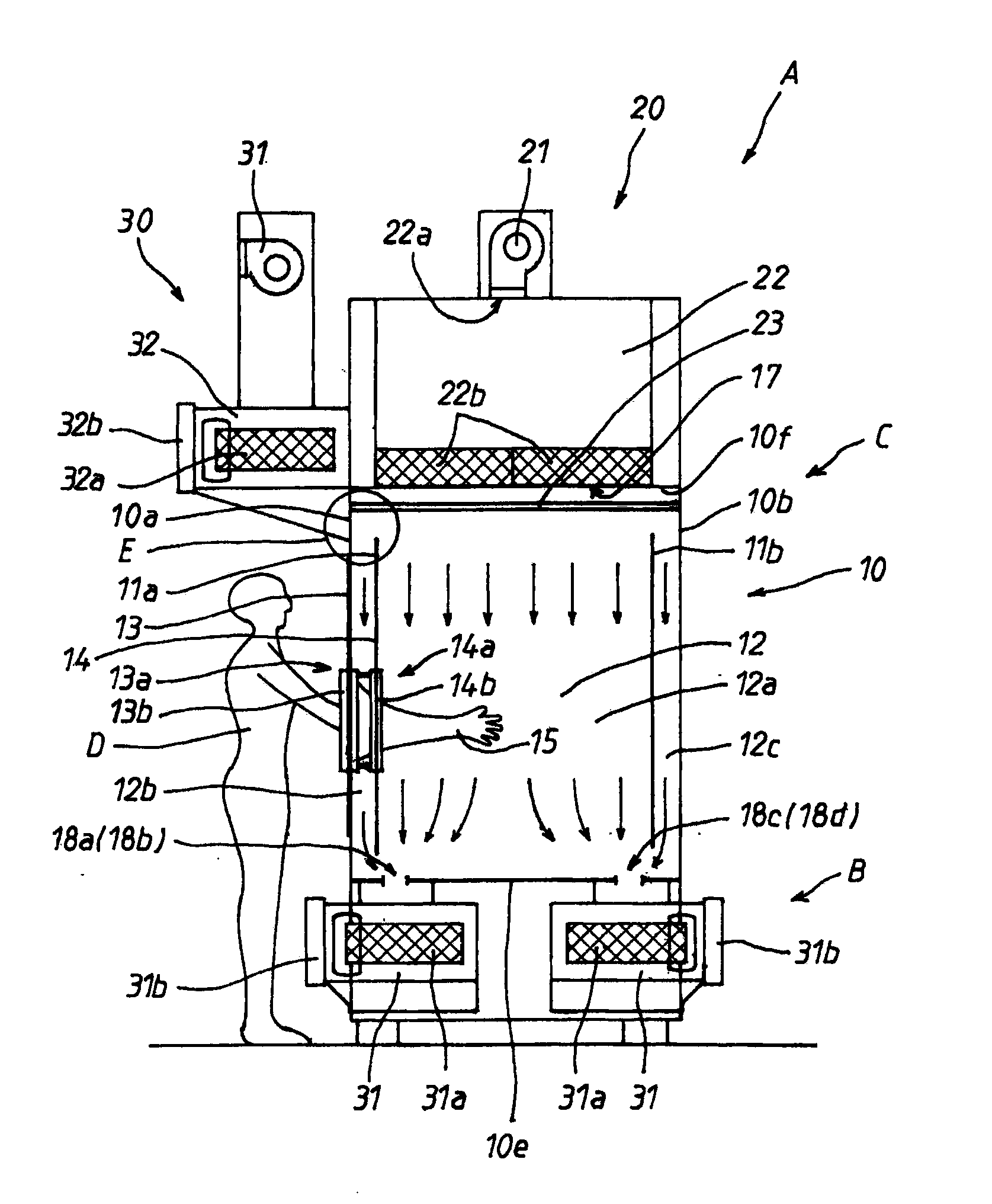
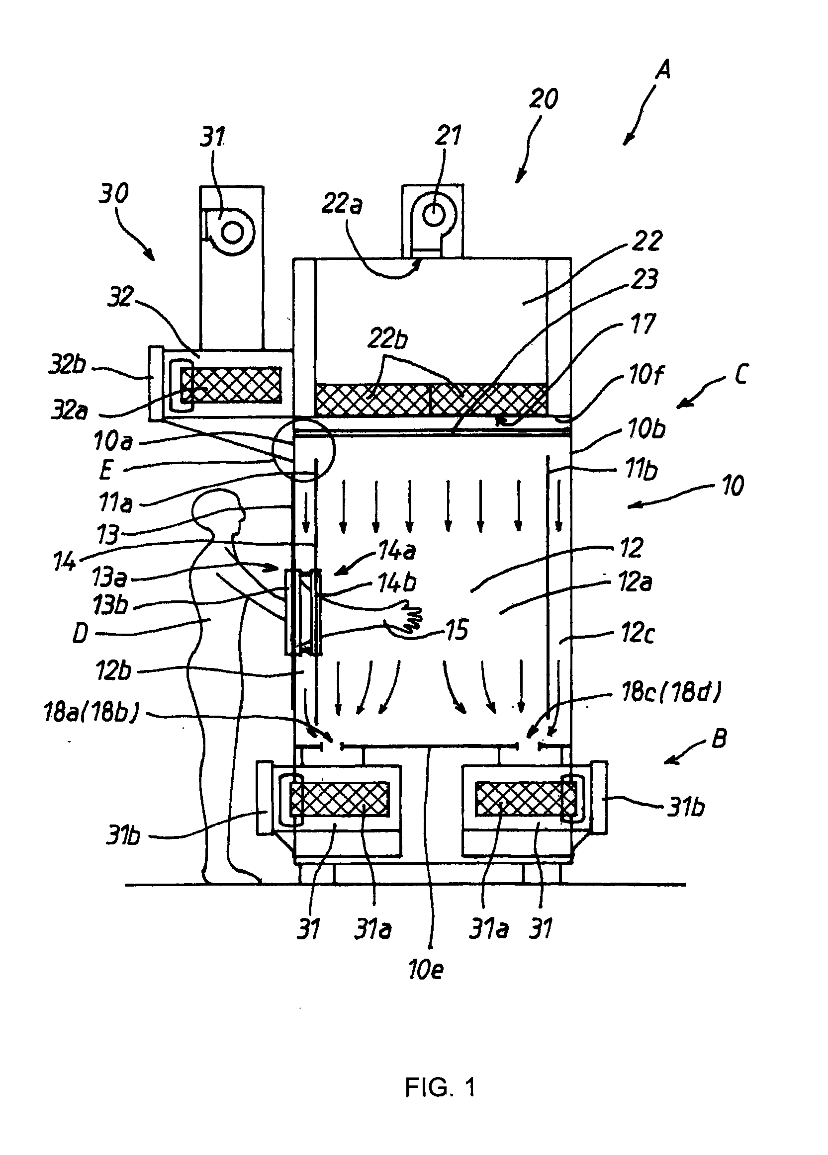
[0140]FIG. 1 is an outline diagram illustrating an inside of the isolator device according to the present invention when seen from a side face, and the isolator device A is composed of a rack B placed on a floor surface and an isolator main body C placed on this rack B.

[0141]The rack B has its periphery covered by a wall material made of a stainless metal plate, and four (only two of them are shown) air-discharge primary filter units 31 (which will be described later), electric components and a machine room (not shown) are accommodated therein.

[0142]The isolator main body C is provided with a chamber 10, an air feed mechanism 20, and an air discharge mechanism 30.

[0143]The chamber 10 is formed of a box body constituted by stainless metal plates and is shielded in an airtight manner from the outside environment where a worker D performs a work except an air inlet and an air outlet which are limited. This chamber 10 is provided with a spray nozzle for washing liquid for washing the in...

second embodiment

[0207]A second embodiment of the isolator device according to the present invention will be described on the basis of the attached drawings. As illustrated in FIGS. 9 to 11, the isolator device A is composed of the rack B placed on a floor surface and the isolator main body C placed on this rack B.

[0208]The rack B has its periphery covered by a wall material made of a stainless metal plate, and four housings 220 to each of which a filter unit 210 for air purification (hereinafter referred to as a filter unit 210) is to be attached, electric components and a machine room 230 are accommodated therein. On the front face and the rear face of this rack B, an opening / closing door 221 for replacing the filter unit 210 from each of the housings 220 is provided in the sealing manner and capable of opening / closing.

[0209]In the four housings 220, the two housings 220 accommodated on the front face side of the rack B communicate with each other and the two housings 220 accommodated on the rear ...

embodiment 2a

(Embodiment 2A of Filter Unit for Air Purification)

[0222]Here, the structure of the filter unit 210 will be described. In FIG. 12, the filter unit 210 is a rectangular cylindrical body having a hollow part therein and is provided with the cylindrical body 211 made of a stainless metal plate and two HEPA filters 212.

[0223]The cylindrical body 211 is composed of a top plate 211a, a bottom plate 211b, and two lateral plates 211c, and a front face and a rear face are left open as the air discharge port portion 213 having a rectangular shape. In the top plate 211a, the air inlet portion 214 opened in a longitudinally state along a boundary line 211d where the face of the air discharge port portion 213 and the top plate 211a cross each other is provided.

[0224]Each of the two HEPA filters 212 is composed of a filter 212a formed by bending a filtering material made of a glass fiber in a wavy shape and a rectangular outer frame 212b holding the peripheral edge portion of this filter 212a. Th...


PUM

PropertyMeasurementUnit
Fractionaaaaaaaaaa
Lengthaaaaaaaaaa
Flexibilityaaaaaaaaaa

Abstract

An isolator device having a work chamber, air supply means for supplying air of a unidirectional airflow traveling from an upper part to a lower part in the work chamber, and air discharge means for discharging air of the unidirectional airflow from a lower part of the work chamber are provided, and moreover, a bulkhead provided in parallel with a peripheral wall portion of the work chamber along the air of the unidirectional airflow and longitudinal air outlets opened along a width direction of a lower end portion in a lower part of the lower end portion of the bulkhead and attached so as to oppose an air inlet portion by a filter unit for air purification is provided.

Description

TECHNICAL FIELD[0001]The present invention relates to an isolator device and particularly to an isolator device with a high level of safety which can be used in a work in which the inside is kept in an aseptic state and in a work for handling a substance which might affect a human body inside.BACKGROUND ART[0002]In a work performed in a clean atmosphere such as a work in a manufacturing stage of a semiconductor and an electronic component or a work in a manufacturing stage of pharmaceuticals, for example, the work is performed in a clean work environment where the inside is kept in an aseptic and dustless state so that contaminants do not intrude from the outside environment. If the work environment in which such work is performed is small-sized, an isolator device in which a chamber or the like sealed from the outside environment is used and a worker can perform the work through a glove or a half suit from outside this chamber is used. Such isolator devices are particularly called ...

Claims


Application Information

Patent Timeline
IPC IPC(8): B01D46/00
CPCB01L1/04B08B15/02B08B15/026B25J21/02F24F3/1607B08B2215/003Y10S55/18B01D46/0091B01D46/0098B01D46/12B08B15/023B01D46/00F24F3/163
Inventor KAWASAKI, KOJIMIYAMOTO, MINORUTODA, TOSHINAGA
Owner AIREX
Why Eureka
Try Eureka