Connector

a technology of connecting rods and connectors, applied in the direction of coupling contact members, coupling device connections, printed circuits, etc., can solve the problems of difficult to provide highly pliant, reliable and durable spring pieces, and the thickness of spring pieces has reached the limits of width and thickness, so as to reduce the size and profile of connectors. , the effect of low connector profil

Active Publication Date: 2015-07-23
JAPAN AVIATION ELECTRONICS IND LTD +1
View PDF23 Cites 68 Cited by
  • Summary
  • Abstract
  • Description
  • Claims
  • Application Information

AI Technical Summary

Benefits of technology

[0018]The present invention enables a spring piece of a shell that contacts a ground contact of a mating connector to be made pliant,

Problems solved by technology

However, spring pieces have reached the limits of thickness and width.
Therefore, i

Method used


Image

  • Connector
  • Connector
  • Connector

Examples


Embodiment Construction

[0049]Embodiments of the present invention will be described below.

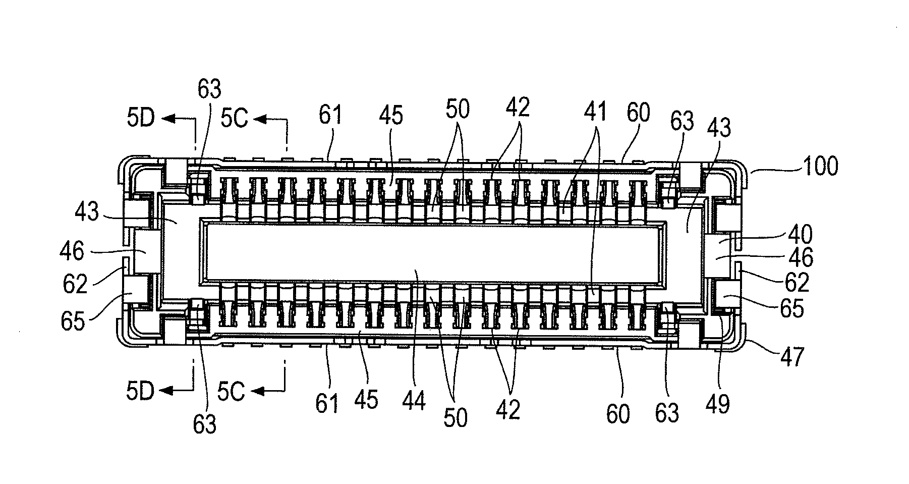
[0050]FIGS. 5A to 5D and 6A and 6B illustrate one embodiment of a connector according to the present invention. The connector 100 is a connector used for electrically interconnecting circuit boards face to face (board-to-board connector) and acts as a receptacle connector.

[0051]The connector 100 includes a housing 40, a large number of contacts 50 arranged and held in the housing 40, and a pair of shells 60 attached around the housing 40. Components of the connector 100 will be described first.

[0052]As illustrated in FIGS. 7A, 7B, 8A and 8B, the housing 40 is a thick plate having a rectangular outside shape and is made of resin. Pair of grooves 41 are formed in the upper surface of the housing 40 along the long sides of the rectangle and contact insertion holes 42 are formed across the grooves 41 at a predetermined pitch in an array in the direction in which the grooves 41 extend. The ends of one of the grooves 41 ar...


PUM


Abstract

A connector includes a housing, contacts arranged and held in the housing, and a shell attached around the housing. The shell is made from a plate and includes an elongated part extending along a sidewall of the housing and a spring piece adapted to contact a ground contact of a mating connector. The spring piece includes a base part protruded from the elongated part in the direction perpendicular to the direction in which the elongated part extends and bent so that its front end is positioned inward from the sidewall, an intermediate part extended from the front end of the base part in the direction in which the elongated part extends, and a contact tip extended from a front end of the intermediate part in the direction perpendicular to the direction in which the elongated part extends. The intermediate part is spaced away from an inner surface of the sidewall and the contact tip is positioned further inward from the inner surface than the intermediate part and a front end of the contact tip is directed to the side from which the mating connector is inserted. The spring piece of the shell can be made pliant even though the profile of the connector is low. Thus, connector profile reduction can be achieved.

Description

TECHNICAL FIELD[0001]The present invention relates to a connector that provides electrical connection.BACKGROUND ART[0002]Connectors for electrically interconnecting circuit boards in a face-to-face relation (board-to-board connectors) are traditionally being used. FIGS. 1 and 2 illustrate a configuration described in Japanese Patent Application Laid Open No. 2012-252785 (published on Dec. 20, 2012, hereinafter referred to as Literature 1), which is an example of such conventional connectors. Illustrated in FIGS. 1 and 2 are a connector (receptacle connector) 10 designed to be mounted on a circuit board, not depicted, and a mating connector (plug connector) 20 designed to be mounted on another circuit board, not depicted, and to be mated with the connector 10. FIG. 2 illustrates a cross-sectional structure of the connector 10 and the mating connector 20 mated together.[0003]The connector 10 includes a housing 11, contacts 12a, 12b held by the housing 11, and a pair of shells 13a, 13...

Claims


Application Information

Patent Timeline
IPC IPC(8): H01R12/71H01R13/6597
CPCH01R13/6597H01R12/716H01R12/73H01R13/516H01R13/648H01R13/6582H01R13/2435H01R13/6594H01R13/20H01R12/732H01R13/631
Inventor TAKENAGA, YUICHIKAMATA, KAZUSHI
Owner JAPAN AVIATION ELECTRONICS IND LTD
Why Eureka
Try Eureka