
Non-Invasive Monitoring of Tissue Mechanical Properties

a tissue mechanical and non-invasive technology, applied in the field of measuring tissue mechanical properties, can solve the problems of insufficient resolution, non-invasive technologies, and inability to accurately distinguish between disease states

Inactive Publication Date: 2015-07-30
UNIVERSITY OF PITTSBURGH +3
View PDF6 Cites 20 Cited by
  • Summary
  • Abstract
  • Description
  • Claims
  • Application Information

AI Technical Summary

Benefits of technology

The invention is a system for monitorying mechanical properties of tissue using a probe and a main unit. The probe has light sources and photodetectors, and the main unit drives the light sources, collects the data from the detectors, and processes and displays the measurements. The system can transmit the data wirelessly to a processing and monitoring unit. The method involves exposing tissue to light, measuring the reflectance of the light, and analyzing and manipulating the reflectance signal to isolate differences in the tissue's mechanical properties. The invention can be utilized as a basis for modifying or designing other embodiments for carrying out the same purposes.

Problems solved by technology

Traditionally, measuring the mechanical properties of tissues can be invasive, most sampling occurs by taking biopsies of specific tissue areas.
Non-invasive technologies have been developed but they do not provide enough resolution to distinguish between disease states.
As such, these techniques may be too insensitive a measure for a clinician to provide timely intervention in the instance of a developing problem.
MRI is unable to ascertain a distinction between any of the other stages of liver disease, such that the early detection of fibrosis is difficult.
Likewise, less sensitive monitoring techniques may also hinder the ability of physicians or other healthcare providers to study the progress of disease / healing of tissue.

Method used


Image

  • Non-Invasive Monitoring of Tissue Mechanical Properties
  • Non-Invasive Monitoring of Tissue Mechanical Properties
  • Non-Invasive Monitoring of Tissue Mechanical Properties

Examples


Embodiment Construction

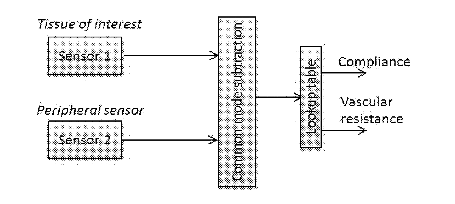
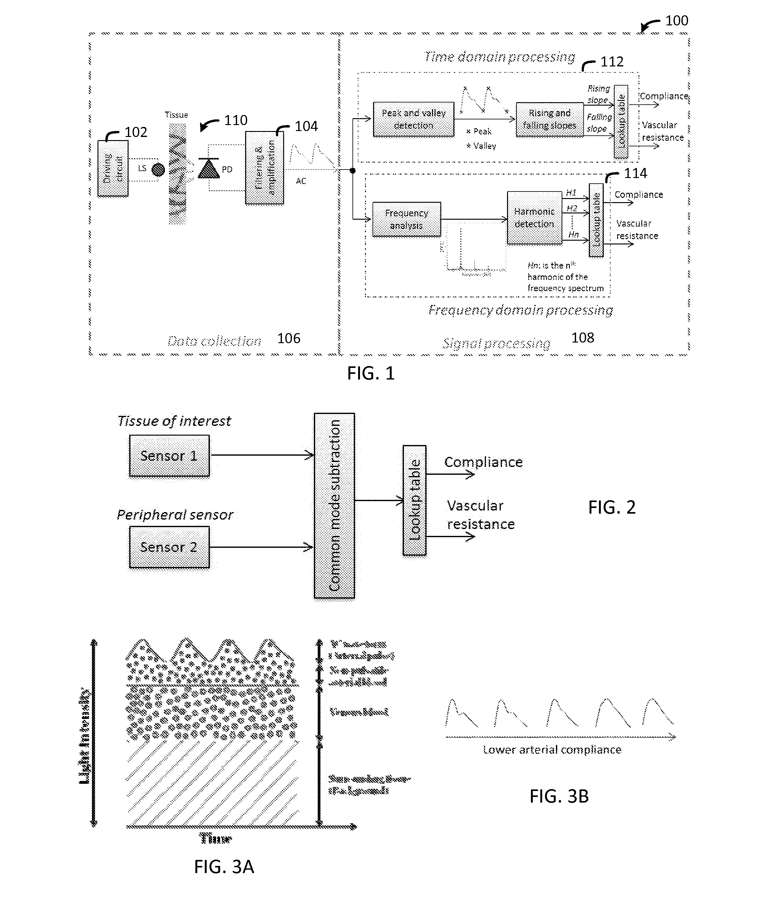
[0011]These and other needs in the art are addressed in one embodiment by a tissue mechanical property monitoring system comprising a probe and a main unit. The probe further comprises light sources and one or more photodetectors. The main unit drives the light sources, collects the data from the detectors, and then processes and displays the measurements. In some embodiments the main unit may transmit the data wirelessly to a processing and / or monitoring unit which may comprise a personal computing device (e.g., computer, smart-phone, tablet, and the like).

[0012]An additional embodiment comprises a method for measuring tissue mechanical properties in vivo using light sources, photodetectors, and data collection / manipulation. The method may comprise exposing tissue to light at different wavelengths generated by light sources such as light emitting diodes, measuring the reflectance of the light via a photodetector to produce a reflectance signal. Analyzing and manipulating the reflec...


PUM


Abstract

Methods and apparatuses for a tissue mechanical property monitoring system are disclosed herein. In one embodiment, a tissue mechanical property monitoring system is disclosed. The tissue mechanical property monitoring system may comprise a probe, wherein the probe comprises a light source and a photodetector; and a main unit, wherein the main unit comprises a microcontroller and wireless transmitter. The probe may be hermetically sealed and may be capable of being implanted onto tissue. The photodetector may be capable of collecting reflectance data from the light emitted by the light source. The reflectance data may be capable of being sorted and processed into tissue mechanical property data such as tissue compliance, vascular resistance, and the like for the tissue illuminated with the probe.

Description

CROSS-REFERENCE TO RELATED APPLICATIONS[0001]This application claims benefit of U.S. Provisional Application Ser. Nos. 61 / 932,575 entitled “Non-Invasive Monitoring of Tissue Mechanical Properties” and 61 / 932,567 entitled “Arterial and Venous Oxygenation Method and Apparatus”, both of which were filed Jan. 28, 2014 and are incorporated herein by reference in their entirety.[0002]This application is also related to U.S. patent application Ser. No. 14 / 608,145 filed currently herewith and entitled “Arterial and Venous Oxygenation Method and Apparatus”, which is incorporated herein by reference in its entirety.STATEMENT REGARDING FEDERALLY SPONSORED RESEARCH OR DEVELOPMENT[0003]This invention was made with government support under 5R01-GM077150 awarded by National Institutes of Health (NIH). The government has certain rights in the invention.BACKGROUND OF THE INVENTION[0004]1. Field of the Invention[0005]The present embodiments relate to measuring tissue mechanical properties in vivo, an...

Claims


Application Information

Patent Timeline
IPC IPC(8): A61B5/00A61B5/02
CPCA61B5/0084A61B5/6847A61B5/4878A61B5/02007A61B5/4244A61B5/445A61B5/02416A61B5/026A61B5/0833A61B5/14546A61B5/14551A61B5/1459
Inventor AKL, TONY J.COTE, GERARD L.WILSON, MARK A.ERICSON, MILTON NANCEHANKS, JOHN P.
Owner UNIVERSITY OF PITTSBURGH
Learn More