

Veress needle
a needle and venous technology, applied in the field of venous needles, can solve the problems of high iatrogenic complications, high rate of penetration of venous needles, morbidity and even mortality, and achieve the effect of preventing the exposure of the sharp distal poin
- Summary
- Abstract
- Description
- Claims
- Application Information
AI Technical Summary
Benefits of technology
Problems solved by technology
Method used
Image

Examples
Embodiment Construction
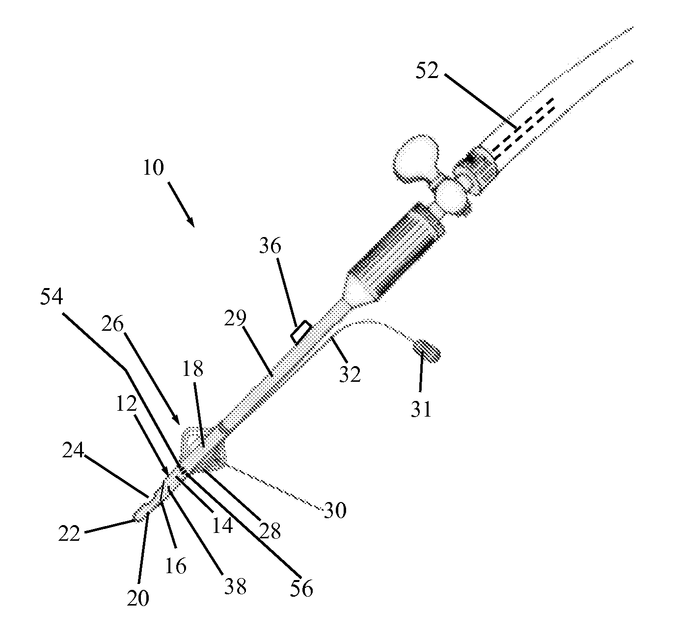
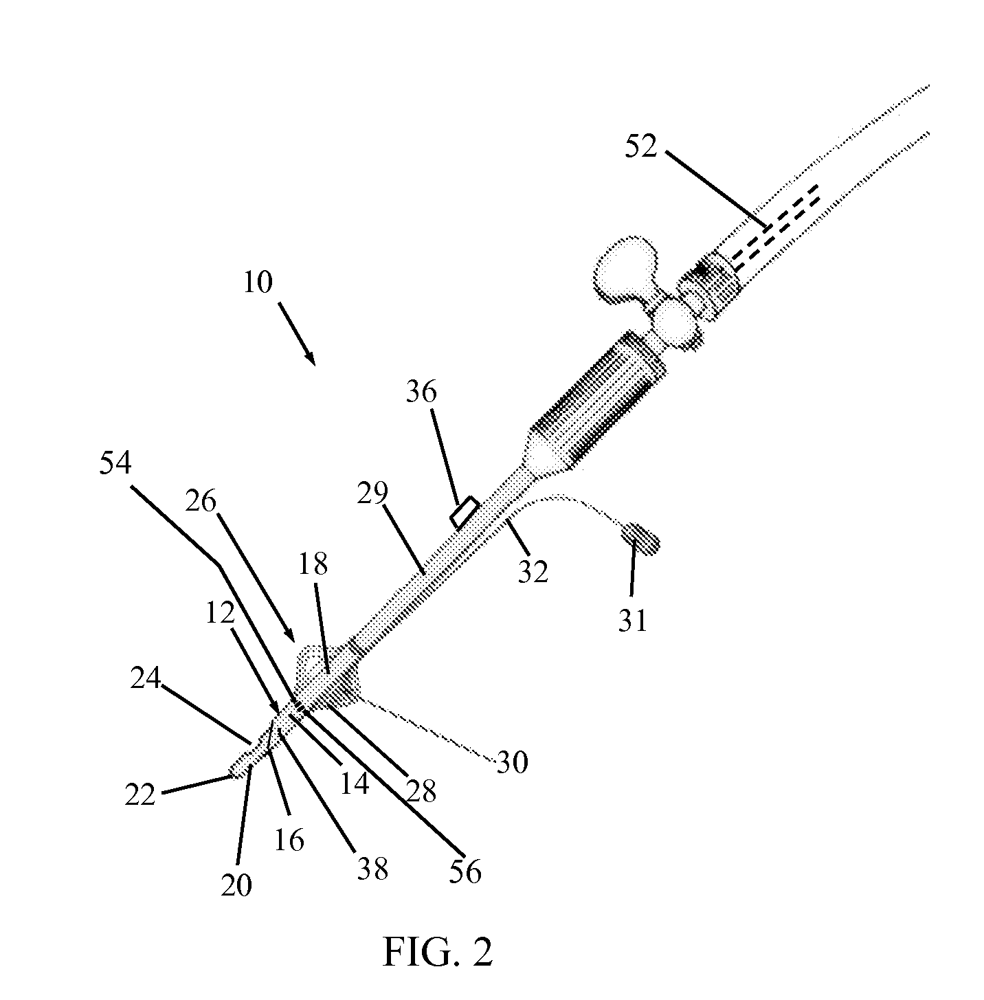
[0022]Reference is now made to FIG. 2, which illustrates a Veress needle 10, constructed and operative in accordance with a non-limiting embodiment of the present invention.
[0023]Veress needle 10 includes an outer needle 12 having a shaft 14 and a sharp distal point 16. The sharp distal point 16 and a distal portion 18 of shaft 14 are configured to penetrate tissue (not shown). A spring-loaded, inner cannula 20 (also referred to as a piston 20) is disposed in outer needle 12. Cannula 20 has a dull tip 22 and a gas exit aperture 24 formed near a distal end of cannula 20. Outer needle 12 has an outwardly expandable portion 26 located on the distal portion 18 of shaft 14. Expandable portion 26 may be configured to expand radially outwards.
[0024]In the illustrated embodiment of FIG. 2, expandable portion 26 includes flexible, deformable slats 28. For example, a distal portion of slats 28 may be joined to shaft 14, whereas a proximal portion of slats 28 may extend from a tube 29 which sl...
PUM
 Abstract
Description
Claims
Application Information