Elastic chuck

a technology of elastic chucks and chucks, applied in the direction of chucks, mechanical equipment, manufacturing tools, etc., can solve the problems of less precise structure, and achieve the effect of high precision, cost saving, and simple structur

Inactive Publication Date: 2015-07-30
HURISE
View PDF9 Cites 10 Cited by
  • Summary
  • Abstract
  • Description
  • Claims
  • Application Information

AI Technical Summary

Benefits of technology

[0008]The pulling block of the elastic plate can be connected to a shaft. When the shaft is pulled by a force-applying device, it drives the pulling block of the elastic plate, so that the holders perform elastic deformation and become inclined toward the through hole, thereby driving the jaws to come close to each other and firmly hold a workpiece. As compared to the conventional devices, the disclosed elastic chuck has a simple structure and limited parts, so its process of manufacturing and assembling are time-saving and cost saving, and the resultant structure is highly precise.

Problems solved by technology

However, such configuration is structurally complicated and needs numerous parts, so its manufacturing and assembling are time-consuming and costly, and the resultant structure tends to be less precise due to errors happening during the process of manufacturing and assembling.

Method used


Image

  • Elastic chuck
  • Elastic chuck
  • Elastic chuck

Examples


Embodiment Construction

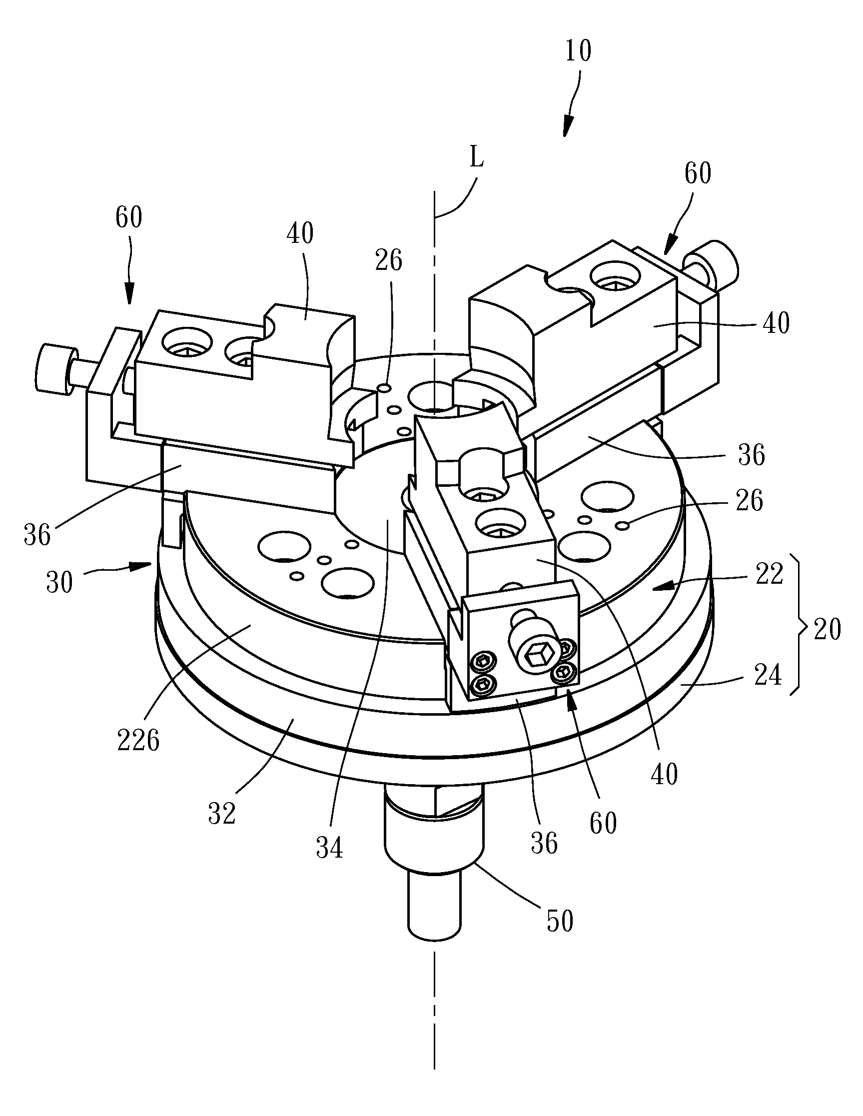
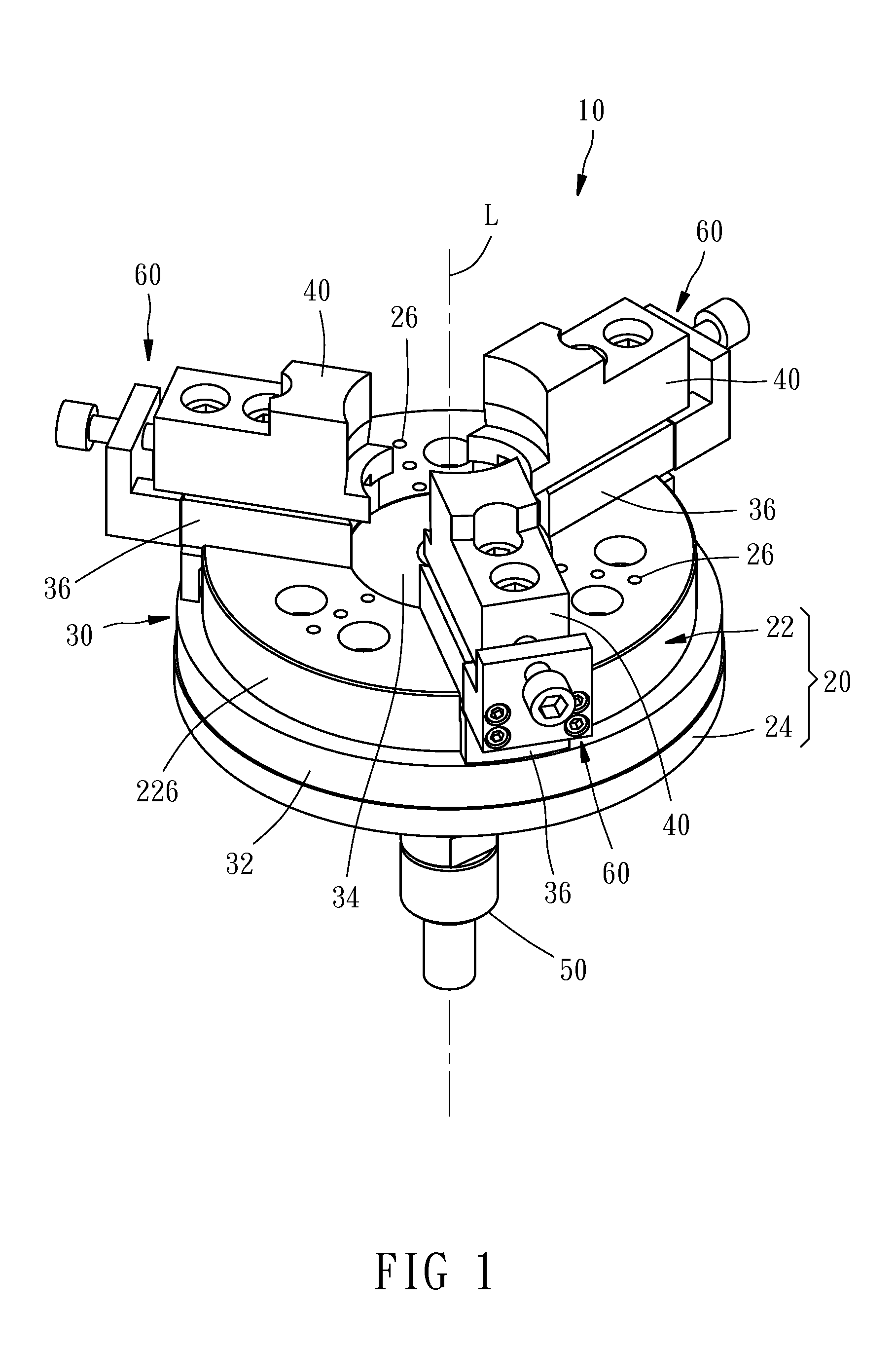
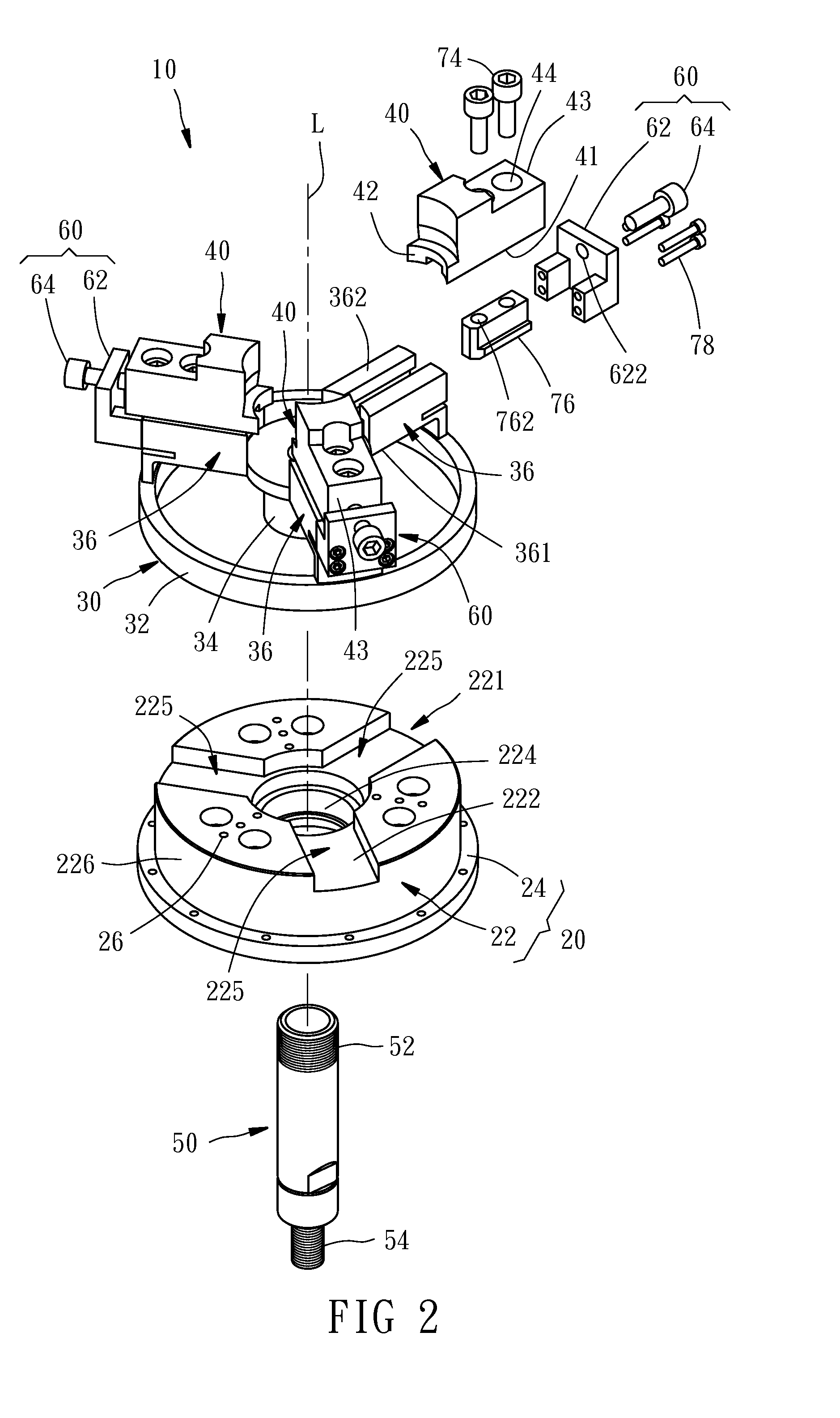
[0015]Referring to the accompanying drawings, according to one preferred embodiment of the present invention, an elastic chuck 10 comprises a base plate 20, an elastic plate 30, three jaws 40, and three retaining units 60. The elastic chuck 10 is connected to a shaft 50 such that it can receive the pulling force from the shaft 50 to hold a workpiece firmly (not shown).

[0016]The base plate 20 has a disk-like main body 22 and an annular flange 24. The main body 22 has a radial depressed portion 221, an upper surface 222 in the depressed portion 221, a lower surface 223 reverse to the upper surface 222, and a through hole 224 running between the upper surface 222 and the lower surface 223. An imaginary central axis L is defined by the through hole. The depressed portion 221 is communicated with the through hole 224 and has three accommodating sections 225 radially distributed around the through hole 224. The flange 24 is integratedly raised from the outer peripheral surface 226 of the ...


PUM

PropertyMeasurementUnit
pulling forceaaaaaaaaaa
elastic deformationaaaaaaaaaa
elasticaaaaaaaaaa

Abstract

An elastic chuck includes a base plate, an elastic plate and jaws. The base plate has a through hole running between upper and lower surfaces thereof. The elastic plate has a fixing ring fixed to the base plate, a pulling block that can move along a central axis of the through hole, and holders radially extending from the pulling block toward the fixing ring. Each of the holders has a top surface facing the upper surface of the base plate across a radial gap. The jaws are mounted at top surfaces of the holders, respectively. The pulling block of the elastic plate receives a pulling force along the central axis to drive the jaws to hold a workpiece firmly. The elastic chuck has a simple structure and limited parts, so its process of manufacturing and assembling are time-saving and cost saving, and the resultant structure is highly precise.

Description

BACKGROUND OF THE INVENTION[0001]1. Technical Field[0002]The present invention relates to a clamping device, and more particularly to an elastic chuck.[0003]2. Description of Related Art[0004]As described in Taiwan Patent No. M359385, a known chuck comprises a base plate that is fixed to a machine and centrally formed with a through hole and a plurality of jaw units installed on the base plate. The chuck typically has three or four jaw units, each of which comprises a sliding block slidably attached to the surface of the base plate, a jaw movably fixed to the sliding block, and a rotary member deposited inside the base plate. The rotary members of the jaw units are driven to rotate a shaft that is located in the through hole. When the shaft is driven by the machine, it moves axially to drive the sliding blocks to move, thereby making the jaws come close to each other and hold a workpiece firmly.[0005]Many conventional chucks are similar configured with the shaft driving the rotary m...

Claims


Application Information

Patent Timeline
Patent Type & Authority Applications(United States)
IPC IPC(8): B23B31/32
CPCB23B31/32B23B31/16283B23B31/18B23B2270/06Y10T279/31
Inventor CHANG, JUNG-FENGCHANG, JUNG-SHENG
Owner HURISE
Why Eureka
Try Eureka