Shoe Part Forming by Injection Moulding and Insert Thereof
a technology of injection moulding and shoe parts, which is applied in the field of shoe parts forming by injection moulding and insert thereof, can solve the problems of complex and expensive moulding, unsuitable inserts, and inability to produce several shoe parts, and achieve the effect of increasing the degree of freedom for forming shoe parts
- Summary
- Abstract
- Description
- Claims
- Application Information
AI Technical Summary
Benefits of technology
Problems solved by technology
Method used
Image
Examples
first embodiment
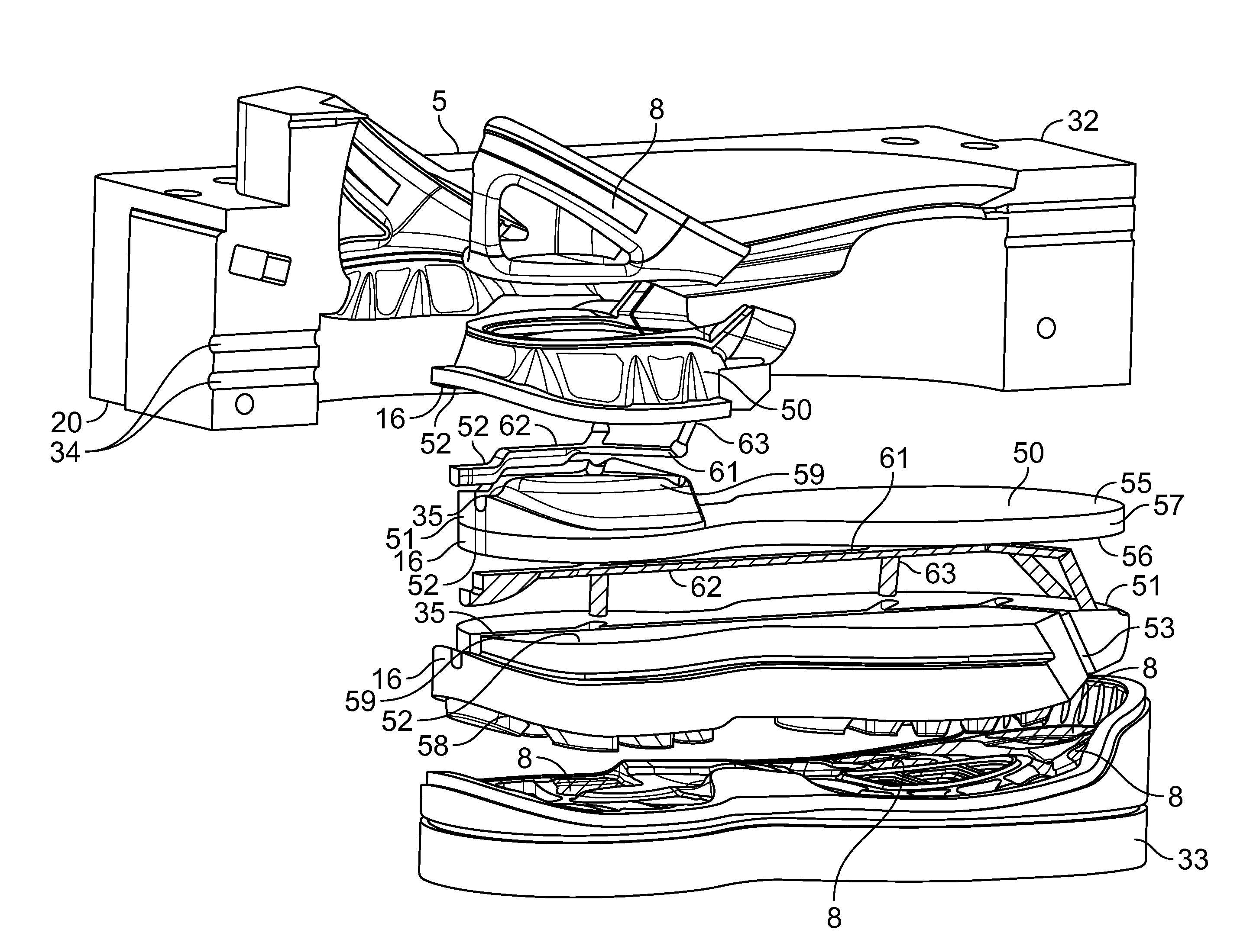
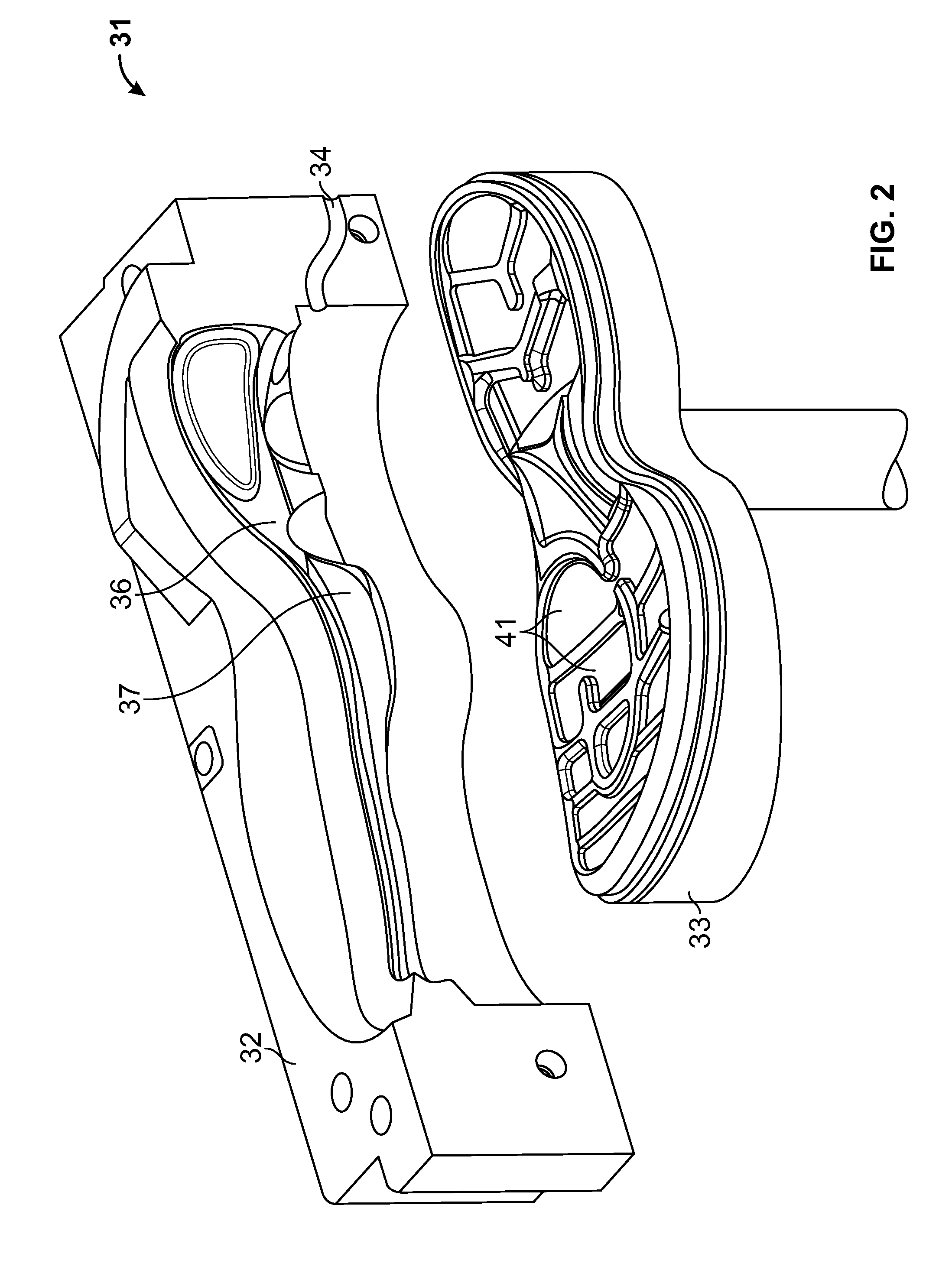
[0058]The entire body of the sole part shaping insert 16 is placed inside the injection chamber and is releasably mounted in the treat pattern of the bottom piston 33. The first injection with polyurethane is made through a sprue channel 34. The polyurethane will flow through an injection channel in the insert and inside the mould. The polyurethane will stay in the first cavity 36 and surround the U-shaped heel of the upper 2 to build a heel cap 5. After the first injection, the two side frames are moved horizontally away from the lasted upper, which now has a heel cap bonded to it and the lasted upper 2 is lifted from the mould. The insert 16 is removed from the upper by the operator and the sprue of the polyurethane heel cap is removed. The insert 16 comprises two parts; an upper insert part 50 and a lower insert part 51. The two parts are separated in order to remove the cured material in an injection channel placed in the interface of the two insert parts 51, 50. This first embo...
second embodiment
[0067]FIG. 5 shows the insert 16 according to the invention; the insert 16 may follow after the heel cap as shown in FIG. 4 has been produced or it may be the first insert placed in order to produce parts of the sole. A segmented more density sole 12 can be made by injecting polyurethane through the injection channel 35. The cavity 36 comprises two separate areas each communicating with a side channel 53 of the insert 16. The channels 53 of the insert are made in the surface of the lower insert part 51 and comprise horizontally and vertically oriented channel parts. The upper insert part 50 covers the injection channel 35 placed in the lower insert part 51. The drawing also shows the print 61 of the whole injection path. The insert comprises two side channels directed vertically downwards having their outlets at the lower first surface 58 of the lower insert part 51. The melt is directed into the cavity 36, placed in the bottom piston 33 and delimited by the lower first surface 58 a...
third embodiment
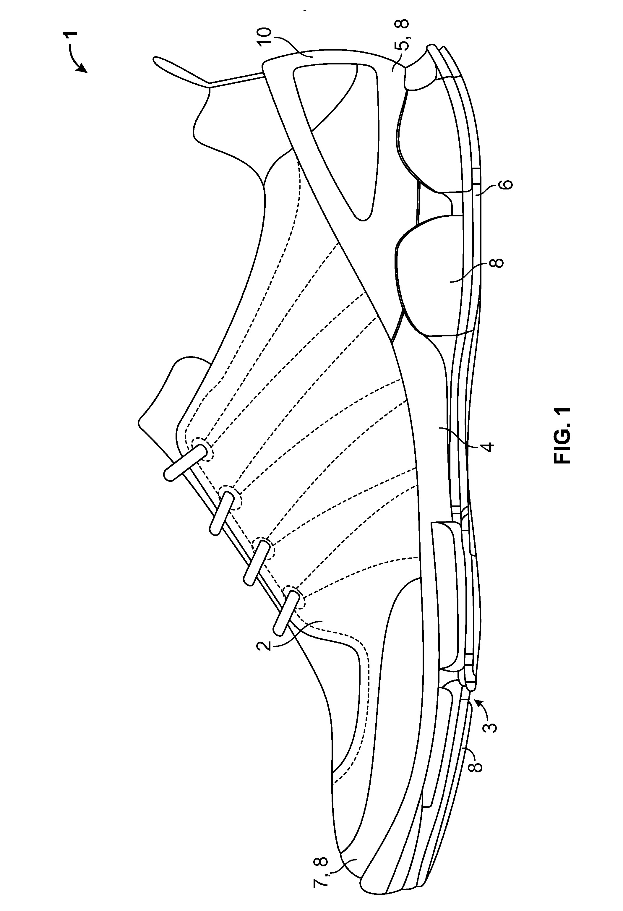
[0068]FIG. 6 shows an insert 16 according to the invention comprising an injection channel 35 and several side channels 53. Four side channels 53 are shown in this example; however, it could be more. The side channels 53 can also point upwards and not only downwards. In case the side channels are pointing upwards, they will of course run through the upper insert part 50. However, in this example the side channel 53 open up at the lower first surface 58 of the lower insert part 51. Thereby, the melt is injected into the cavity providing four shoe parts 8. The drawing also shows a print 61 of the cured melt in the injection path and the final produced sole 12 comprising the shoe parts 8. The shoe parts are specific parts of the outsole 6 having other mechanical properties than the rest of the outsole 6.
[0069]However, the removed insert 16 could be exchanged with another insert 16, whereby a new specific cavity is provided into which a material is injected. Thereby, another shoe part(s...
PUM
| Property | Measurement | Unit |
|---|---|---|
| Fraction | aaaaa | aaaaa |
| Electrical resistance | aaaaa | aaaaa |
Abstract
Description
Claims
Application Information
 - R&D
- Intellectual Property
- Life Sciences
- Materials
- Tech Scout
- Unparalleled Data Quality
- Higher Quality Content
- 60% Fewer Hallucinations
Browse by: Latest US Patents, China's latest patents, Technical Efficacy Thesaurus, Application Domain, Technology Topic, Popular Technical Reports.
© 2025 PatSnap. All rights reserved.Legal|Privacy policy|Modern Slavery Act Transparency Statement|Sitemap|About US| Contact US: help@patsnap.com


