Negative Polarity on the Nanofiber Line

a nanofiber and negative polarity technology, applied in the field of negative polarity on the nanofiber, can solve the problems of fibrous sheets or webs formed via centrifugal spinning technology that exhibit defects

Active Publication Date: 2015-07-30
KIMBERLY-CLARK WORLDWIDE INC
View PDF2 Cites 20 Cited by
  • Summary
  • Abstract
  • Description
  • Claims
  • Application Information

AI Technical Summary

Problems solved by technology

However, fibrous sheets or webs formed via centrifugal spinning technology often exhibit defects as the fibrous sheets or webs are formed on a co

Method used


Image

  • Negative Polarity on the Nanofiber Line
  • Negative Polarity on the Nanofiber Line
  • Negative Polarity on the Nanofiber Line

Examples


example 1

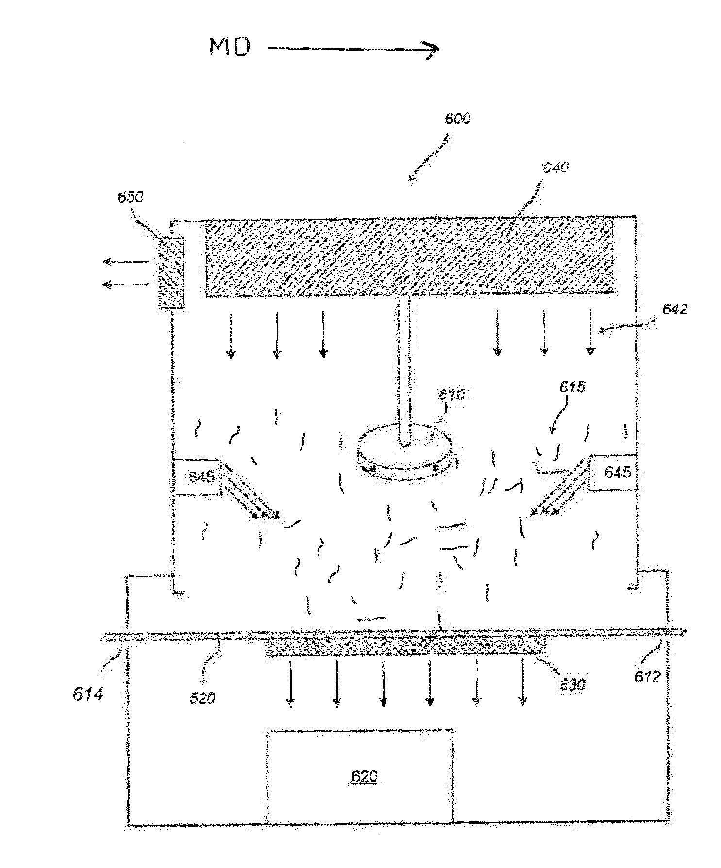
[0063]A fibrous web was formed by dry blending a polypropylene masterbatch. The blend contained 98 wt % polypropylene (Metocene™ MF650Y, Basell Polyolefins), 1.5 wt % peroxide, and 0.5 wt. % sodium stearate. Once formed, the dry-blend was poured in a dry state into the hopper of a centrifugal spinning system (FibeRio® Technology Corporation), which spun the blend into a fibrous web utilizing two centrifugal spinning chambers. The temperature of the extrusion zones of the centrifugal spinning system ranged from 185° C. to 240° C. and the temperature of the hot runner (which flows the melt into the spinneret) was 240° C. Further, the flow rate from the melt pump into the hot runner was 8 milliliters per minute. The spinneret also rotated at a rate of 6000 RPM and was set to a temperature of 440° C. The first centrifugal spinning chamber included a perforated forming plate having a positive charge of 20 kilovolts and the second centrifugal spinning chamber included a performed forming ...


PUM

PropertyMeasurementUnit
Electric potential / voltageaaaaaaaaaa

Abstract

A centrifugal spinning system and method for forming a fibrous web containing nanofibers, microfibers, or a combination thereof from a molten polymer composition or an aqueous spinning solution is provided. Through careful control over the arrangement of the system, a fibrous web can be formed that is relatively defect free. To help accomplish this feature, at least two centrifugal spinning chambers, each containing a charged forming plate, are utilized. To minimize the present of defects in the fibrous web, the charge applied to the first spinning chamber has a polarity that is opposite the polarity of the charge applied to the second spinning chamber.

Description

BACKGROUND OF THE INVENTION[0001]Centrifugal spinning has become an important process for forming fibers, such as nanofibers and microfibers, as it allows the formation of fibers from either a molten polymer composition or from an aqueous spinning solution. Such systems and methods are an improvement over, for example, electrospinning technology, in that the use of organic solvents is avoided with centrifugal spinning. However, fibrous sheets or webs formed via centrifugal spinning technology often exhibit defects as the fibrous sheets or webs are formed on a collecting surface of a centrifugal spinning unit or as the sheets or webs are removed from the centrifugal spinning unit onto a roll via a winder. As such, a need exits for a system and method of forming fibrous sheets or webs via centrifugal spinning that minimizes the amount of defects in the fibrous sheets or webs.SUMMARY OF THE INVENTION[0002]In accordance with one embodiment of the present invention, a fiber-forming syste...

Claims


Application Information

Patent Timeline
IPC IPC(8): D01D5/00
CPCD01D5/0092D01D7/00D01D5/0061D01D5/18
Inventor LAMANAC, ANTHONY L.
Owner KIMBERLY-CLARK WORLDWIDE INC
Why Eureka
Try Eureka