Device for moving members for operating or for closing a window or door frame

a technology for operating or closing windows and doors, applied in the direction of gearboxes, gearing control, gear casings, etc., can solve the problems of material and machining costs, irregular operation of moving devices, and limitations to the overall bulk of such moving devices, so as to reduce the time required for carrying, reduce the cost of operation, and simplify the effect of mounting operations

Inactive Publication Date: 2015-07-30
MASTERLAB S R L UNIPERSONALE
View PDF9 Cites 6 Cited by
  • Summary
  • Abstract
  • Description
  • Claims
  • Application Information

AI Technical Summary

Benefits of technology

[0023]In such a general purpose, a purpose of the present invention is to provide a device for moving members for operating or closing a window or door frame of the type activated by the rotation of the pin of a control lever or handle that is versatile and adaptable to the different types of window or door frames and profile and to the different mounting needs of the control lever or handle, in particular, to the different values that can be taken by the distance between the axis of the pin of a lever or handle and the external part of the profile that forms the side of the frame (“entry” or “inlet”).
[0024]Another purpose of the present invention is to provide a device for moving members for operating or closing a window or door frame of the type activated by the rotation of the pin of a control lever or handle that permits to simplify the mounting operations on profiles, reducing the time required to carry them out and reducing the wastage due to operating errors.
[0025]Yet, another purpose of the present invention is to provide a device for moving members for operating or closing a window or door frame of the type activated by the rotation of the pin of a control lever or handle that permits to ensure regular and fluid motion of the moving members and that permits to reduce the risks of the moving members breaking.
[0026]Another purpose of the present invention is to make a device for moving members for operating or closing a window or door frame of the type activated by the rotation of the pin of a control lever or handle that is particularly simple and functional, with low costs.

Problems solved by technology

If errors occur in making such holes, which do not allow the moving device to be aligned with the holes, i.e. the seat of the rotary element intended to couple with the lever or handle pin and the holes intended to be engaged by the fixing members, the profile needs to be discarded and the perforation operations need to be repeated on a new profile.
This involves obvious drawbacks in terms of material and machining costs.
Known moving devices (“macchinette”), as already stated above, are encased in seats obtained in the profile that forms the side of the frame of the movable swing of a window or door frame; this sets limitations to the overall bulk of such moving devices.
Often, therefore, such teeth break, causing “jumping” and irregular operation of the moving devices and often requiring their total replacement.

Method used


Image

  • Device for moving members for operating or for closing a window or door frame
  • Device for moving members for operating or for closing a window or door frame
  • Device for moving members for operating or for closing a window or door frame

Examples


Embodiment Construction

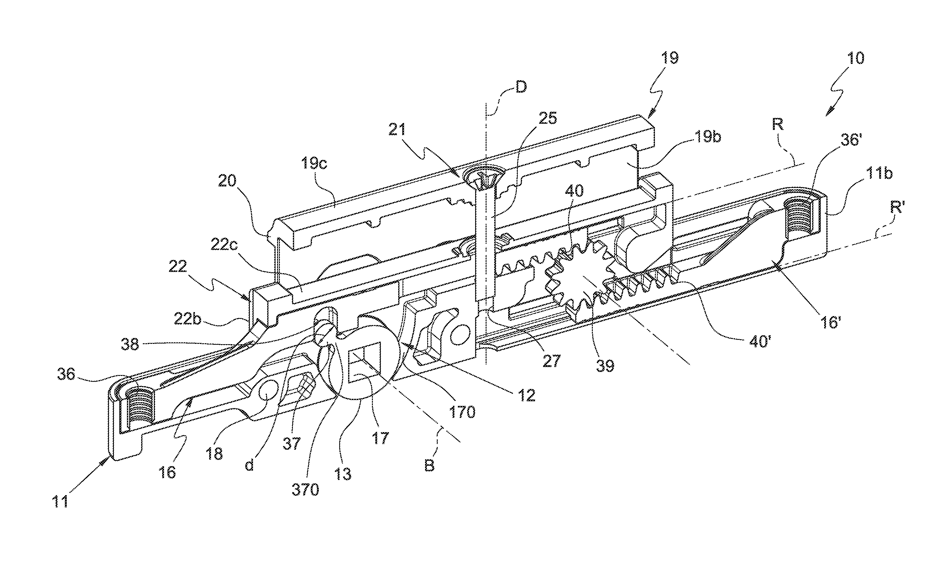
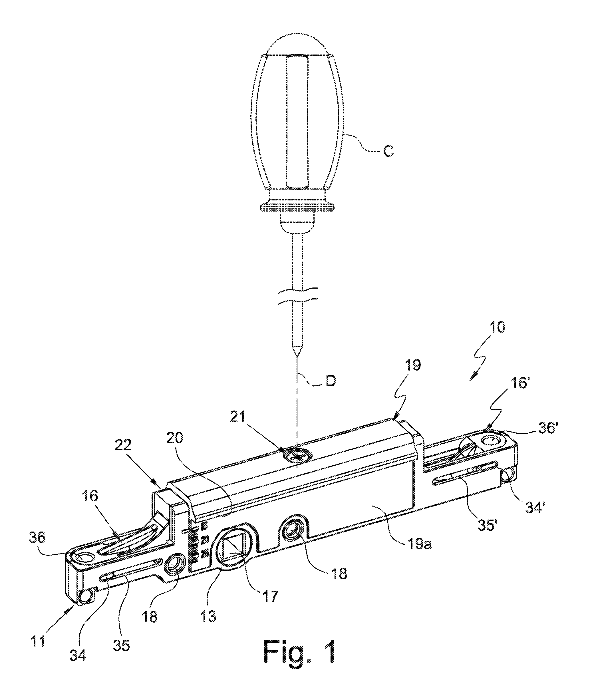
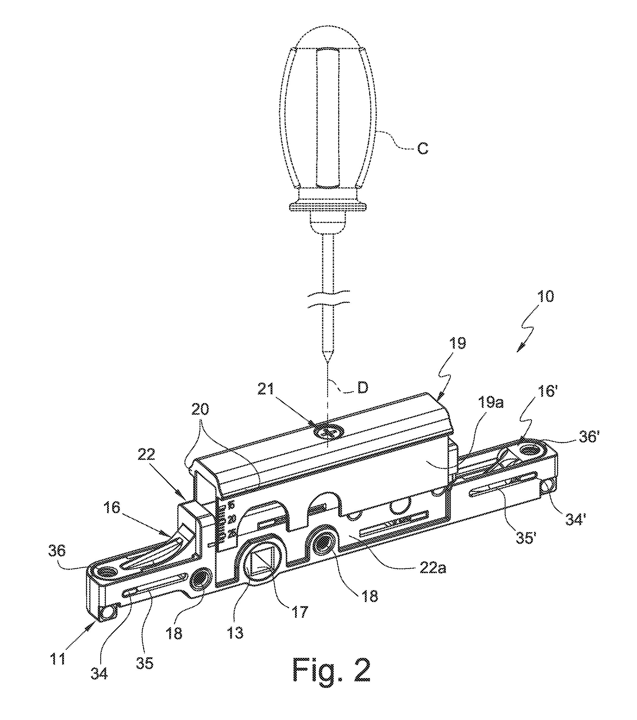
[0041]With reference to the attached figures, a device for moving members for operating or closing a window or door frame, of the type activated by the rotation of the pin of a lever or handle, has been wholly indicated with 10.

[0042]The moving device 10 comprises a supporting and containing body 11 that supports and contains a mechanism 12 for transforming the rotary motion of an element 13, which is intended to be coupled with the pin 14 of a control lever or handle 15 from which it receives the rotary motion, into translational motion of at least one slider 16 along the two opposite senses of the same line R.

[0043]The supporting and containing body 11 is houseable in a seat 101, 201, 301 of a profile 100, 200, 300 constituting a side of a window or door frame movable swing.

[0044]The at least one slider 16 is coupleable with a respective rod for operating or closing the window or door frame movable swing, which rod is housed in a chamber of the same profile 100, 200, 300. In the a...


PUM


Abstract

A device for moving members for operating/closing a window/door frame, activated by rotation of the pin of a lever/handle and a supporting and containing body for transforming the rotary motion of an element to be coupled with the pin of a control lever/handle in translational motion of at least one slider; the supporting and containing body housed in a seat of a profile and the at least one slider coupleable with a rod; an auxiliary body mounted on the supporting and containing body in mutually movable manner along direction (D) parallel to the side of the profile of the swing and orthogonal to direction (R), the auxiliary body having at least one abutment element for positioning the supporting and containing body in the seat along direction (D) and adjustment means for adjustment of the relative position of the auxiliary body and the supporting and containing body along direction (D).

Description

CROSS-REFERENCE TO RELATED APPLICATIONS[0001]The present application claims the priority of Italian Patent Application Nos. MI2014A000128, filed Jan. 30, 2014 and MI2014A000129, Filed Jan. 30, 2014, the contents of which are incorporated herein by reference.FIELD OF THE INVENTION[0002]The present invention refers to a device for moving members for operating or for closing a window or door frame. More specifically, the present invention refers to a device for moving members for operating or closing a window or door frame and of the type activated by the rotation of the pin of a control lever or handle (“square pin”).BACKGROUND OF THE INVENTION[0003]In the field of window or door frames and casings it is known to use handles that are applied to the profile that forms the side of the moveable swings opposite that at which the articulation hinges of the movable swing itself are fixed and the rotation of which handles activates, by means of a suitable moving device housed inside such a s...

Claims


Application Information

Patent Timeline
Patent Type & Authority Applications(United States)
IPC IPC(8): E05F11/14F16H57/031
CPCF16H57/031E05F11/14E05B63/06E05C9/041E05C9/042E05B9/02Y10T74/18568Y10T74/18808Y10T74/2186
Inventor LOPERFIDO, MICHELE
Owner MASTERLAB S R L UNIPERSONALE
Why Eureka
Try Eureka