Illumination device

a technology of illumination device and illumination surface, which is applied in the direction of lighting and heating apparatus, semiconductor devices for light sources, instruments, etc., can solve the problem of not achieving uniform illumination across the illuminated surface, and achieve uniform illumination distribution

Active Publication Date: 2015-07-30
SHARP KK +1
View PDF8 Cites 8 Cited by
  • Summary
  • Abstract
  • Description
  • Claims
  • Application Information

AI Technical Summary

Benefits of technology

[0059]According to a lighting device of an embodiment of the present invention, it is possible to realize a uniform illuminance distribution.

Problems solved by technology

Thus, there is a problem that illuminance uniformity is not achieved across the illuminated surface.

Method used


Image

  • Illumination device
  • Illumination device
  • Illumination device

Examples


embodiment 1

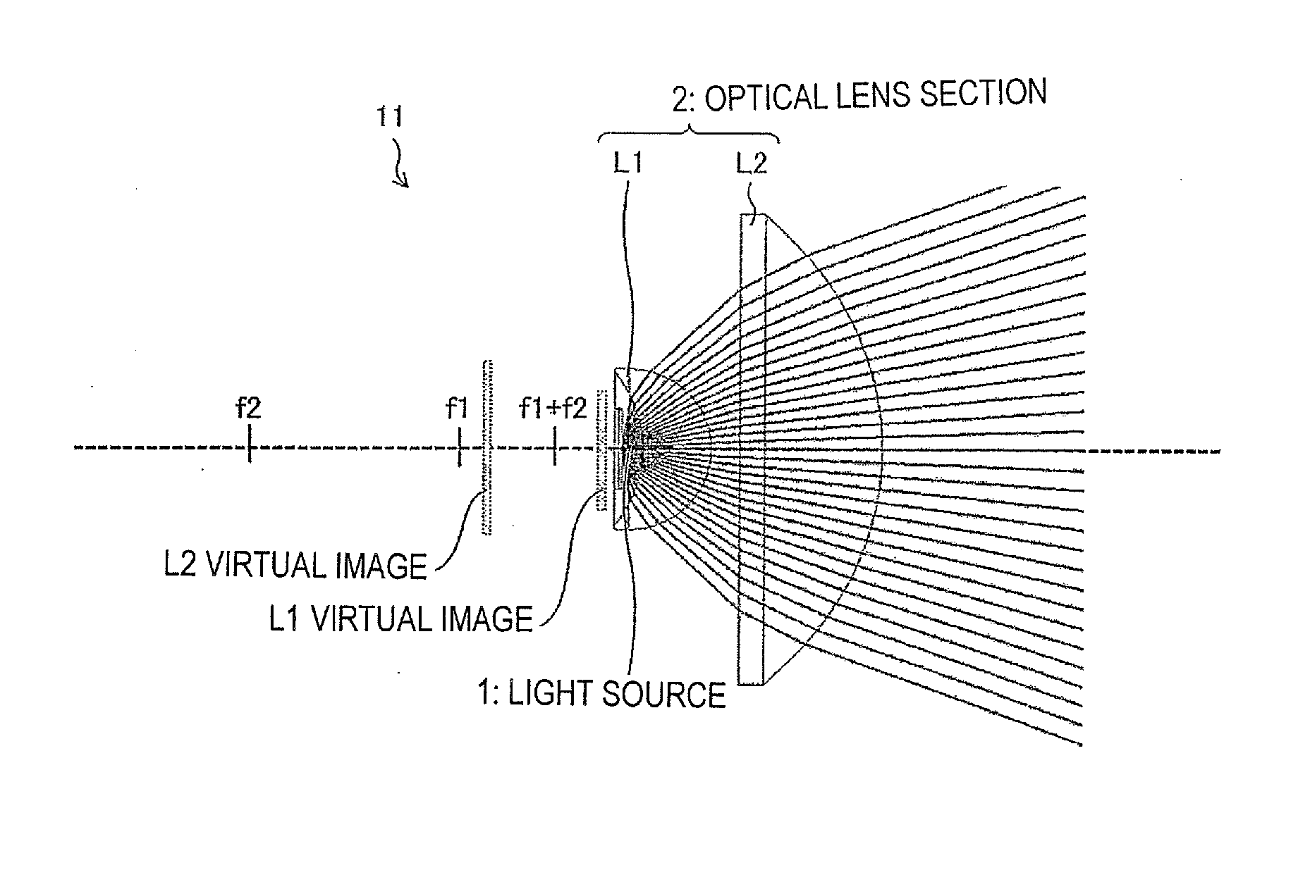
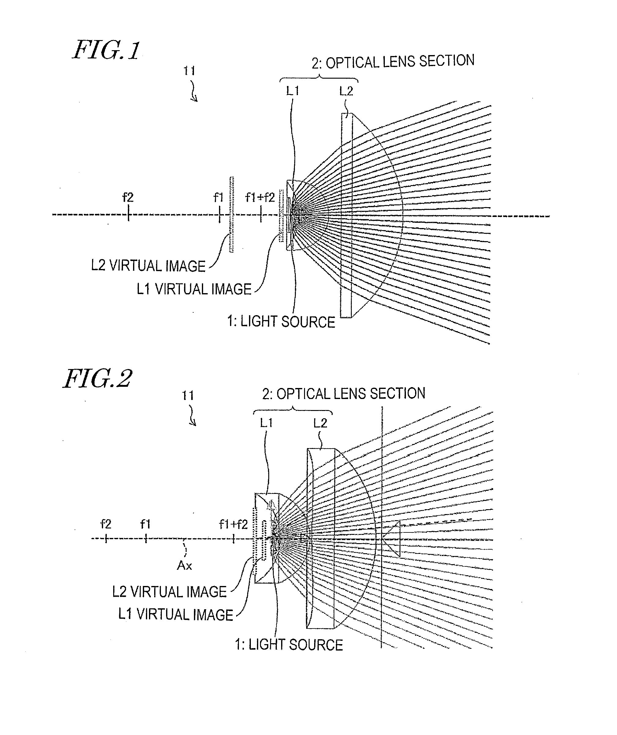
[0123]FIG. 1 and FIG. 2 are diagrams showing the general configuration of a lighting device 11 according to the present embodiment.

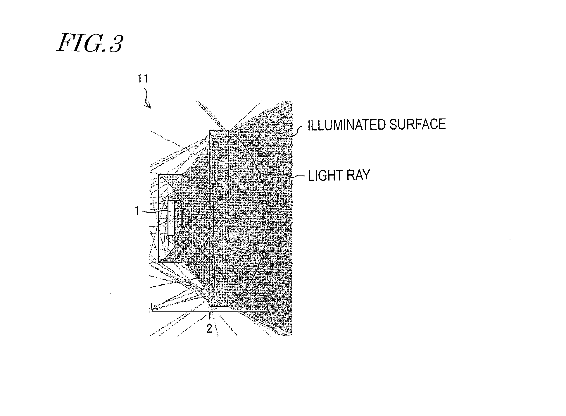
[0124]FIG. 3 is a diagram showing the state of light projection in the lighting device 11 shown in FIG. 2.

[0125](Configuration of Lighting Device) . . . FIGS. 1, 2, and 3

[0126]As shown in FIG. 1, the lighting device 11 includes a light source (light emission section) 1 and an optical lens section 2 provided on the optical axis AX on the light exit surface side, which is the light extraction side, of the light source 1. The lighting device 11 is configured such that light produced by the light source 1 is projected through the optical lens section 2.

[0127]The light source 1 includes a LED emitter. The LED emitter is a surface light emitter which is capable of surface emission. Note that it is not limited to the LED emitter so long as it is a surface light emitter which is capable of surface emission.

[0128]The optical lens section 2 includes two optical le...

embodiment 2

[0235]Another embodiment of the present invention will be described below. Note that, for the sake of convenience of description, components which have identical functions as those of Embodiment 1 are designated by the same reference numerals, and detail description thereof is herein omitted.

[0236](Configuration of Lighting Device) . . . FIGS. 14 and 15

[0237]FIG. 14 is a diagram showing a general configuration of a lighting device 12 according to the present embodiment.

[0238]FIG. 15 is an enlarged view of the major portion A shown in FIG. 14.

[0239]The lighting device 12 has a configuration where optical lenses 3, 4 are further added on the light exit side of the optical lens section 2 of Embodiment 1 as shown in FIG. 14.

[0240]That is, where the optical lens section 2 is referred to as the first optical lens section, the lighting device 12 has a configuration in which the second optical lens section formed by at least two optical lenses (optical lenses 3, 4) is provided on the light ...

embodiment 3

[0256]Still another embodiment of the present invention will be described below. Note that, for the sake of convenience of description, components which have identical functions as those of Embodiments 1 and 2 are designated by the same reference numerals, and detail description thereof is herein omitted. In an example described in this section, two optical lenses of the optical lens section 2 are integrated together.

[0257](Configuration of Lighting Device) . . . FIGS. 20 and 21

[0258]FIG. 20 is a diagram showing a general configuration of a lighting device 13a according to the present embodiment.

[0259]FIG. 21 is a diagram showing a general configuration of a lighting device 13b according to the present embodiment.

[0260]The lighting device 13a shown in FIG. 20 is an example where the optical lenses L1, L2 are integrally molded to form an optical lens section 22.

[0261]Specifically, the optical lenses L1, L2 are integrally molded with a die using a resin such as an acrylic material to ...


PUM


Abstract

A lighting device (100) includes: a surface light source (1); a first lens (L1) having a first focal point (F1), the first lens being provided on the light exit surface side of the surface light source; and a second lens (L2) having a second focal point (F2), the second lens being provided on a light exit surface side of the first lens, the surface light source, the first lens, and the second lens being configured such that a first virtual image (I1) is formed by the first lens and a second virtual image (I2) is formed by the second lens, wherein the first virtual image (I1) is formed between the second focal point (F2) and the first lens, and the second focal point (F2) is on a side opposite to the light source side relative to a predetermined focal position f′.

Description

TECHNICAL FIELD[0001]The present invention relates to a lighting device which includes a surface light source.BACKGROUND ART[0002]A known example of common lighting devices is a lighting device 900 shown in FIG. 62.[0003]The lighting device 900 has a collimating optical system LC which includes a meniscus lens L1 and an aspherical lens L2 and is configured such that a LED light source 10 is placed at the focal position of this optical system as shown in FIG. 62.[0004]Here, light emitted from a point on the optical axis AX of the LED light source 10 is collimated light which is parallel to the optical axis AX as shown in FIG. 62. On the other hand, since the LED light source 10 is a surface light source rather than a point light source, there is light emitted from a location away from the optical axis AX. The light emitted from a location away from the optical axis AX travels in a direction which is different from the optical axis AX and therefore reaches a place which is different f...

Claims


Application Information

Patent Timeline
Patent Type & Authority Applications(United States)
IPC IPC(8): F21V5/04F21K99/00
CPCF21V5/04F21Y2101/02F21K9/50F21V5/008G02B19/0014G02B19/0061F21Y2115/10F21K9/60
Inventor UCHIDA, TATSUOSUZUKI, YOSHITOKAWAKAMI, TOHRUISHINABE, TAKAHIROEHARA, KATSUNORIHASHIMOTO, YOSHIHIROMATSUOKA, TOSHIKINAKAMURA, KOZOITOH, YASUHISAYAMAMOTO, YOSHITAKAISHII, YUTAKAMONTGOMERY, DAVID
Owner SHARP KK
Why Eureka
Try Eureka