
Energy storage assembly and energy storage element thereof

a technology of energy storage and energy storage elements, applied in indirect heat exchangers, lighting and heating apparatuses, heating types, etc., can solve the problems of large power consumption in activation and operation, and achieve the effect of low hydraulic resistance and great speed

Inactive Publication Date: 2015-07-30
KUNSHAN JUZHONG ELECTRONICS
View PDF54 Cites 3 Cited by
  • Summary
  • Abstract
  • Description
  • Claims
  • Application Information

AI Technical Summary

Benefits of technology

The present invention provides an energy storage assembly and element that offer the benefits of low hydraulic resistance, which allows air to flow through the element without difficulty, and high capacity for heat storage. This design reduces power consumption and cost during peak times and allows for energy reuse at times of low power demands. The cylindrical body shape of the energy storage elements also allows for smooth heat transfer with the air flow. The arrangement of the cylindrical bodies in a variety of forms creates low hydraulic resistance to allow for speedy air flow.

Problems solved by technology

Nevertheless, no matter whether the air-flow generating device is generating cold air or hot air, its activation and operation require large amount of power consumption, which also typically happens at peak times of high demands of power consumption.

Method used


Image

  • Energy storage assembly and energy storage element thereof
  • Energy storage assembly and energy storage element thereof
  • Energy storage assembly and energy storage element thereof

Examples


first embodiment

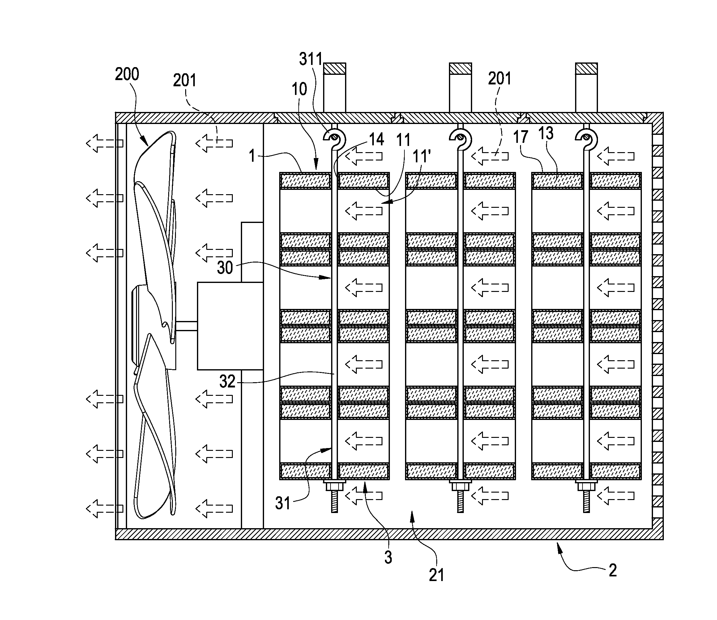
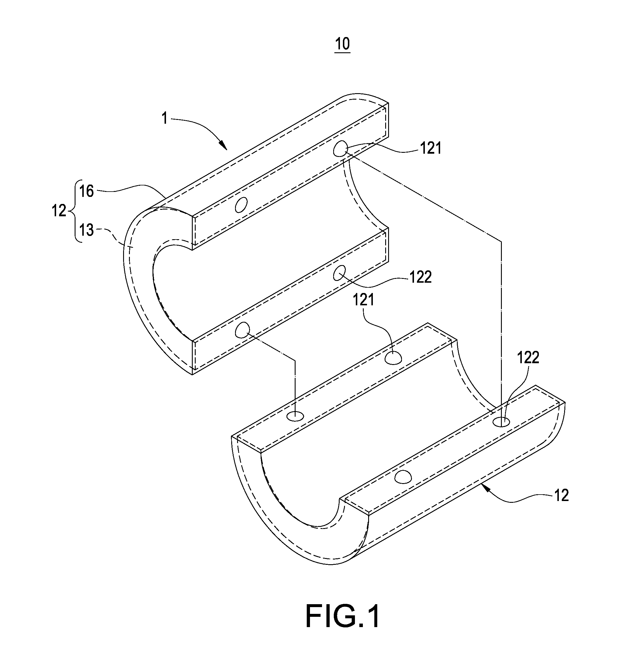
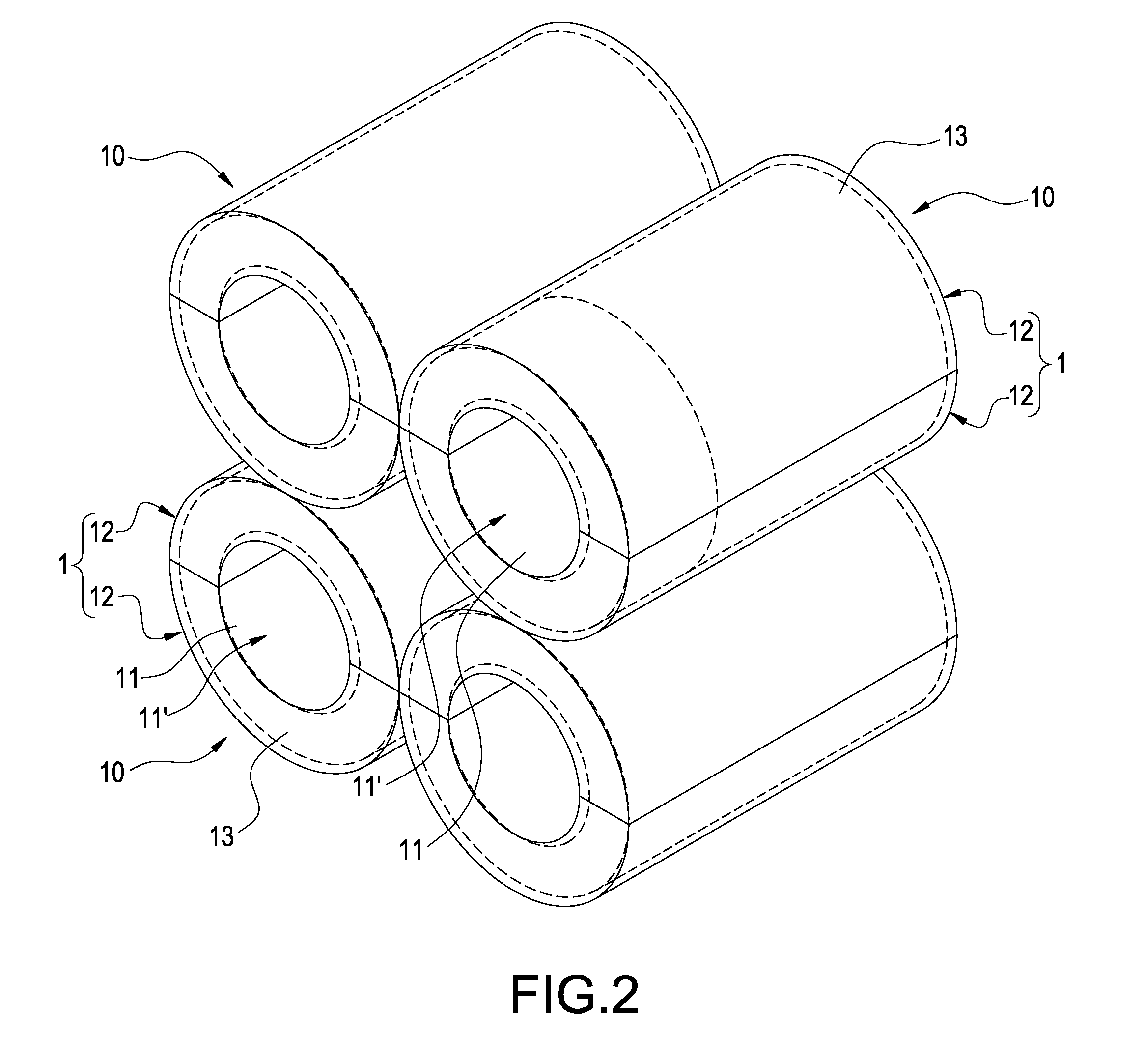
[0032]As shown in FIGS. 1 to 3, according to the energy storage element 10 of the present invention, the cylindrical body 1 includes a channel 11′ formed in an axial direction in an internal thereof. The channel 11′ can be of different shapes in its cross section, such as a circular, triangular, rectangular or multi-angular shape of cross section; in a preferred embodiment, the channel 11′ is preferably a channel with a circular cross section 11. The cylindrical boy is filled with an energy storage material 11 in an internal thereof, and the cylindrical body is constructed by a plurality of curved blocks 12 arranged in a circumference and attached to each other. In addition, each one of the curved blocks 12 includes at least one protrusion 121 formed on one side thereof and at least one groove 122 formed on another side thereof; the at least one protrusion 121 of each one of the curved blocks 12 is inserted into the at least one groove 122 of each one of the curved blocks 12 corresp...

fourth embodiment

[0049]Furthermore, as shown in FIG. 10, in this embedment, the number of the fixation member 30 and the energy storage element 10 is singular. When only one energy storage element 10 is fixed firmly inside the accommodating space 21, since the energy storage element 10 is a cylindrical body 1 and a channel with circular cross section 1 is formed in the internal of the cylindrical body 1, the shape of such single energy storage element 10 can also have the merit of low hydraulic resistance. Accordingly, the energy storage element 10 can be embodied as the structure of the fourth embodiment mentioned above or it can also be embodied as the structure of the other embodiments mentioned above.

[0050]Additionally, as shown in FIG. 4 again, the outer circumferential surface of the cylindrical body 1 includes a pair of through holes formed thereon and arranged opposite to each other; alternatively, as shown in FIG. 5 again, the outer circumferential surface of the cylindrical body includes a...


PUM


Abstract

An energy storage element of an energy storage assembly includes a cylindrical body and a channel formed in an axial direction in an internal thereof; wherein the cylindrical body includes an energy storage material. With the energy storage element having a cylindrical body, the shape of the energy storage element is of the merit of low hydraulic resistance, which allows air flow to pass through the energy storage element(s) smoothly at great speed.

Description

BACKGROUND OF THE INVENTION[0001]1. Field of the Invention[0002]The present invention is related to a thermal storage element, in particular, to an energy storage assembly and an energy storage element thereof.[0003]2. Description of Related Art[0004]During summer time or weather of high temperatures, air conditioners or cooling fans are often used for drawing cooling air into a room, office or confined space internally and while during winter time or weather of low temperatures, heaters or hot-air fans capable of generating heated air are often used in raising the temperature of a room, office or confined space. Nevertheless, no matter whether the air-flow generating device is generating cold air or hot air, its activation and operation require large amount of power consumption, which also typically happens at peak times of high demands of power consumption.[0005]Currently, there have been energy storage materials developed in the market, and such energy storage materials are able ...

Claims


Application Information

Patent Timeline
Patent Type & Authority Applications(United States)
IPC IPC(8): F28D17/02
CPCF28D17/02F28F9/007F24F5/0017F28D20/00F28D2020/0021Y02E60/14
Inventor KUO, DAH-CHYILONG, LINGWANG, APPLE
Owner KUNSHAN JUZHONG ELECTRONICS
Learn More