Fuel rod cladding, fuel rod and fuel assembly

a technology applied in the field of nuclear energy, can solve the problems of loss of stability in the hlmc, low resistance of fuel rods and assemblies in heavy liquid metal melts, and inability to judge the performance of fuel rods, so as to improve the performance characteristics reduce the core hydraulic resistance, and improve the effect of fuel rods and assemblies

Active Publication Date: 2016-08-04
AKME ENG
View PDF5 Cites 2 Cited by
  • Summary
  • Abstract
  • Description
  • Claims
  • Application Information

AI Technical Summary

Benefits of technology

[0016]The objective of the invention is an improvement in the performance characteristics of fuel rods and assemblies as a result of the long-term resistance of the cladding in the environment of a heavy liquid metal coolant such as lead or a eutectic of lead and bismuth.
[0017]The technical result of the invention is an improvement in the performance characteristics of fuel rods and assemblies as a result of the long-term resistance of the cladding in the environment of a heavy liquid metal cool

Problems solved by technology

Unfortunately, the abstract does not reveal the composition of the material of the fuel rod cladding and configuration of the ribs, which does not allow to judge the performance of the fuel rod, in particular, its resistance to HLMC.
Disadvantages of the prior art include low resistance of fuel rods and assemblies in heavy liquid metal melts, which is primarily due to the aluminum low melting point of 660° C.
Furthermore, the rectangular profile cross-section according to the known patent will cause high stress concentrati

Method used


Image

  • Fuel rod cladding, fuel rod and fuel assembly
  • Fuel rod cladding, fuel rod and fuel assembly

Examples


embodiment example

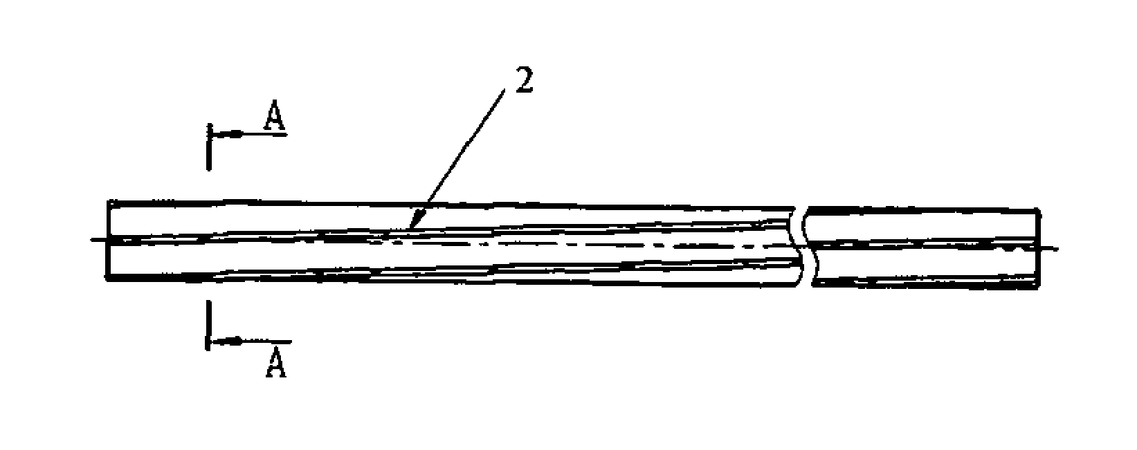
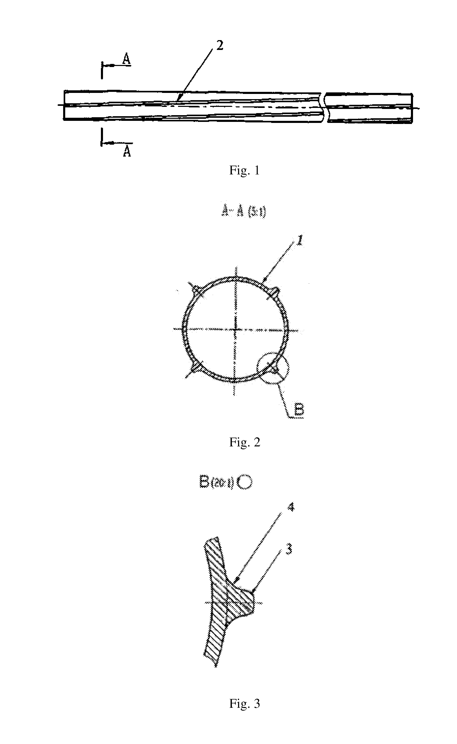
[0050]A tube with 4 spiral ribs was fabricated by cold rolling of billets made of steel EP823-SH for manufacture of the fuel claddings.

[0051]The cladding crest diameter is 13.5 mm, cladding wall thickness is 0.4 mm, cladding inner diameter is 11.2 mm. The ribs have a height of 0.75 mm, rib half-height width is 0.75 mm, rib height-to-thickness ratio is 1.85 mm. The cross-section of the rib was a trapezoid with rounded corners at the trapezoid top with a curvature radius of 0.2 mm, fillet radius of 0.7 mm. The rib opening angle was 30°. The ribs were spiraled with a pitch of 750 mm (left-hand winding).

[0052]Nuclear fuel based on uranium dioxide was placed in the manufactured cladding and the manufactured FRs were sealed with upper and lower tail pieces (plugs).

[0053]To complete the fuel assembly, the assembled FRs were installed in the frame structure with the spacing on a “rib-to-rib” basis and attached in the upper, intermediate and lower grid mounted on the frame structure. The res...


PUM


Abstract

The invention relates to the field of nuclear engineering and can be used in the manufacture of fuel rods and fuel assemblies for heavy liquid metal cooled reactors, and also in the manufacture of fuel rod simulators for use in irradiation devices designed to test the operability of real fuel assemblies. The present gadding of a fuel rod for a heavy liquid metal cooled reactor is in the form of a weldless tubular element h helically-coiled fins disposed on the outer surface of said element, which is made from a ferritic-martensitic chromium-silicon steel with a minimum ferrite grain size of 7 on the GOST 5639 scale, wherein each fin has an opening angle of from 22 to 40 (preferably from 30 to 40) and the cross-section of the fin is in the shape of a trapezoid with rounded corners at the top of the trapezoid and smooth corners at the base of the trapezoid. Also disclosed are a fuel rod comprising the above cladding, and a fuel assembly. The technical result of the invention is an improvement in the performance characteristics of fuel rods and assemblies as a result of the long-term resistance of the cladding in the environment of a heavy liquid metal coolant such as lead or a eutectic of lead and bismuth.

Description

FIELD OF THE INVENTION[0001]The invention relates to the field of nuclear energy and may be used in the manufacture of fuel rods (FR) and fuel assemblies (FA) for reactors with a heavy liquid metal coolant (HLMC), as well as in the manufacture of FR simulators to be used in irradiation devices for real FR performance testing.PRIOR ART[0002]Prior art includes a wide range of fuel rods with cladding designed as a metallic tubular element made of an HLMC-resistant metal or alloy, with at least one rib arranged helically and protruding out of the surface of the tubular element (see. abstract of Publication JPH02163694). The FR according to this patent comprises a cladding with pellets of uranium oxide and plutonium and plugs installed at the ends. Spiral ribs of the cladding are integrated with the tubular element with a predetermined height and number of turns along the entire length of the tube on its outer surface. The ribs help to maintain the distance between the FRs during operati...

Claims


Application Information

Patent Timeline
IPC IPC(8): G21C3/08G21C3/12G21C3/07G21C1/03
CPCG21C3/08G21C3/04G21C3/07G21C3/12Y02E30/40G21C1/03G21C21/02G21C3/30Y02E30/30
Inventor DERUNOV, VIACHESLAV VASILIEVICHMAYOROV, VIKTOR MIHAILOVICHPOMESCHIKOV, PAVEL ANDREEVICHRUSANOV, ALEKSANDER EVGENIEVICHSMIRNOV, ALEKSANDR ALEKSEEVICHSHULEPIN, SERGEY VIKTOROVICHSHARIKPULOV, SAID MIRFAISOVICH
Owner AKME ENG
Why Eureka
Try Eureka