

Mixing device and method for controlling the temperature of a fluid flow
a technology of mixing device and fluid flow, which is applied in the direction of heating types, space heating and ventilation details, domestic heating details, etc., can solve the problems of individual components' cost and energy loss in the mixing valve, and achieve the effect of less expensive and higher energy efficiency
- Summary
- Abstract
- Description
- Claims
- Application Information
AI Technical Summary
Benefits of technology
Problems solved by technology
Method used
Image

Examples
Embodiment Construction
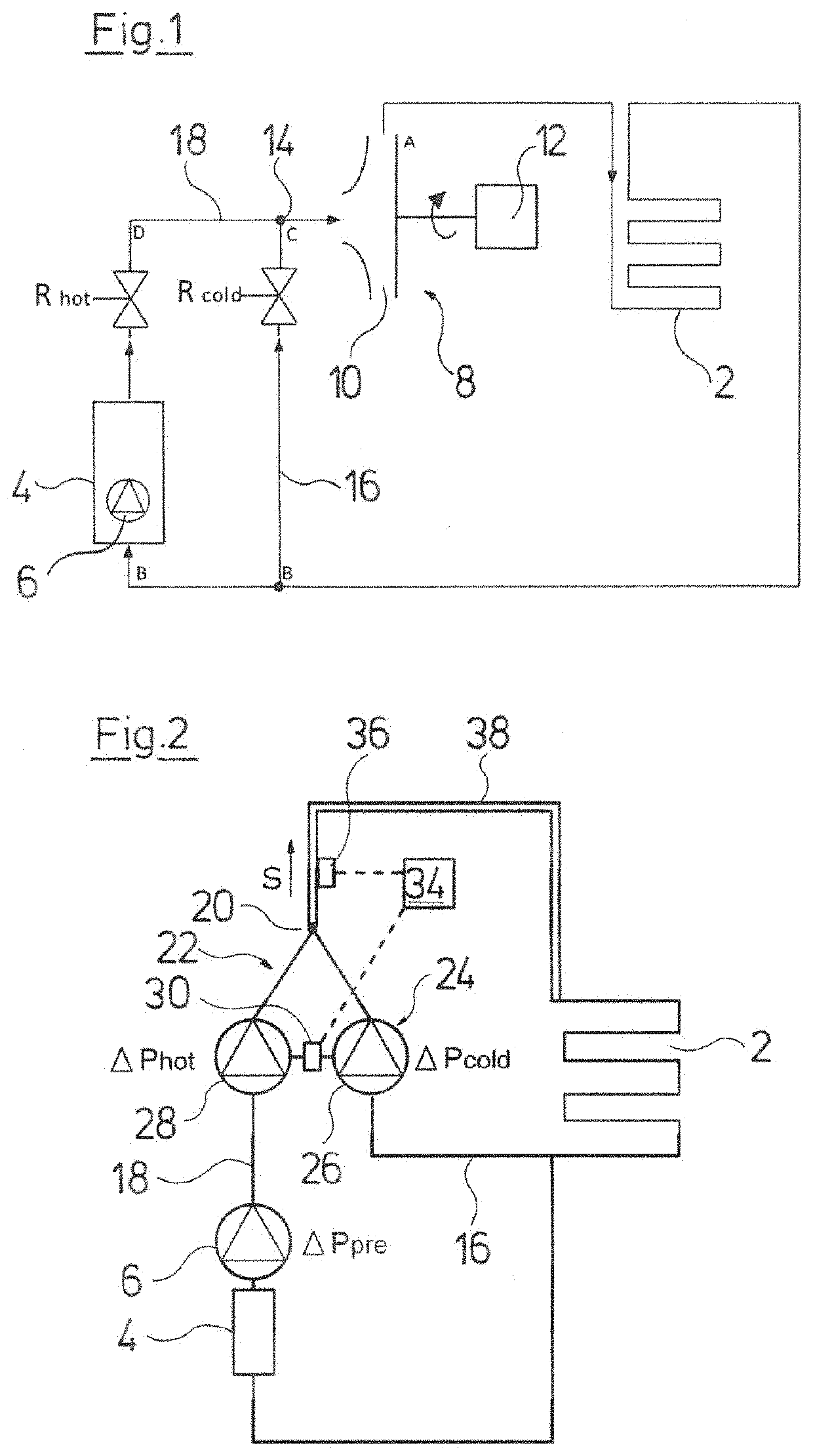
[0049]Referring to the drawings, FIG. 1 schematically shows a conventional heating circuit for a floor heating 2, i.e. a heating circuit according to the state of the art. A heating boiler 4, for example a gas heating boiler with an integrated circulation pump 6 serves as a heat source. Such combinations are known on the market as compact heating facilities. A further circulation pump assembly 8 with an impeller 10 as well as with an electrical drive motor 12 is provided for the floor heating circuit 2. Here, a mixing device is provided since the heating boiler 4 has too high a feed temperature for the floor heating 2, wherein this mixing device has a mixing point 14 which is situated at the suction side of the impeller 10. A return conduit 16 of the floor heating circuit 2 runs out at the mixing point 14. A feed conduit 18, via which the water or heating medium which is heated by the boiler 4 is fed and injected at the mixing point 14 by the pressure produced by the circulation pum...
PUM
 Abstract
Description
Claims
Application Information