
Display panel and method for fabrication thereof

a technology of display panel and flexible substrate, which is applied in the field of display panel, can solve the problems of film on the flexible substrate being damaged, release force may be increased, etc., and achieve the effect of reducing the release force produced and enhancing the success rate of removing the flexible substra

Active Publication Date: 2015-07-30
AU OPTRONICS CORP
View PDF4 Cites 9 Cited by
  • Summary
  • Abstract
  • Description
  • Claims
  • Application Information

AI Technical Summary

Benefits of technology

The invention provides a display panel and a way to make it that makes it easier to remove a flexible substrate. This makes it more likely to be successful. In the display panel, there are openings in the protective layer, which reduces the force needed to remove the flexible substrate. This improves the yield of the display panels and increases the success rate of the manufacturing process.

Problems solved by technology

However, if IC bonding is already completed before removing the flexible substrate, then the hard IC may lead to stress concentration and thus release force may be increased.
Accordingly, the film on the flexible substrate may possibly be damaged in the process of removing the flexible substrate.

Method used


Image

  • Display panel and method for fabrication thereof
  • Display panel and method for fabrication thereof
  • Display panel and method for fabrication thereof

Examples


Embodiment Construction

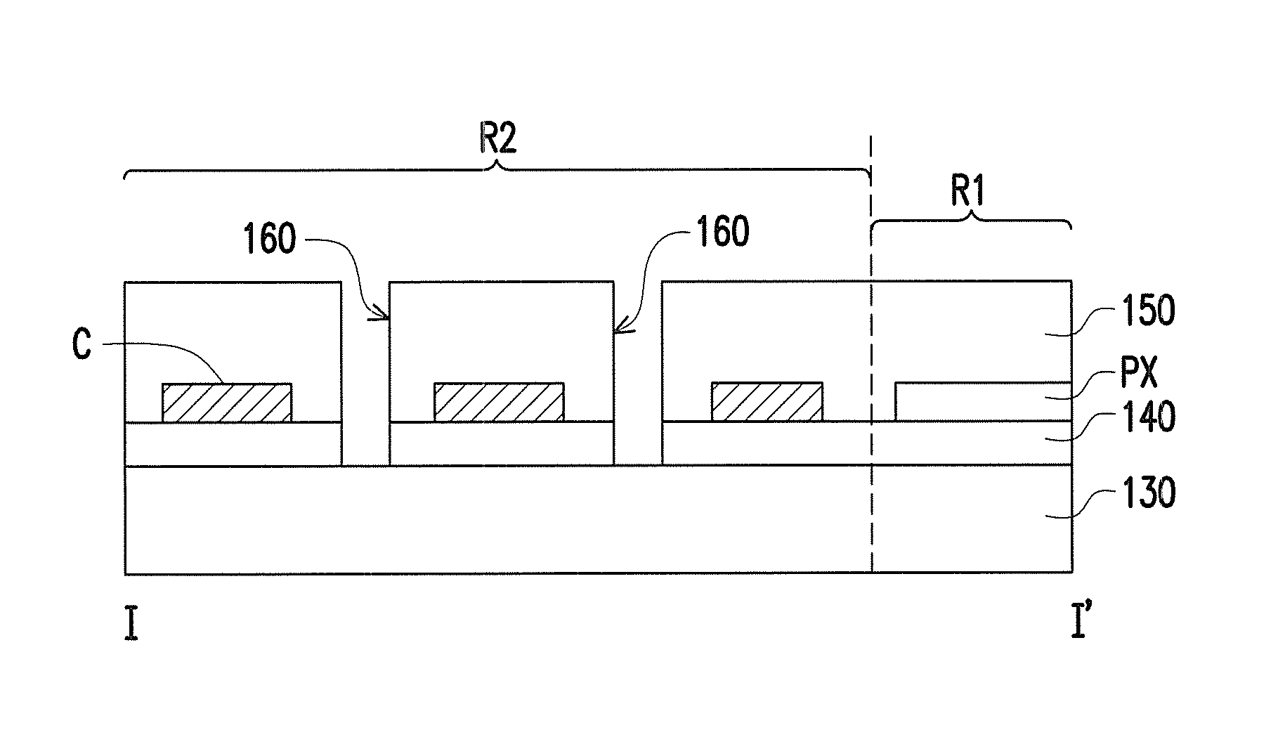
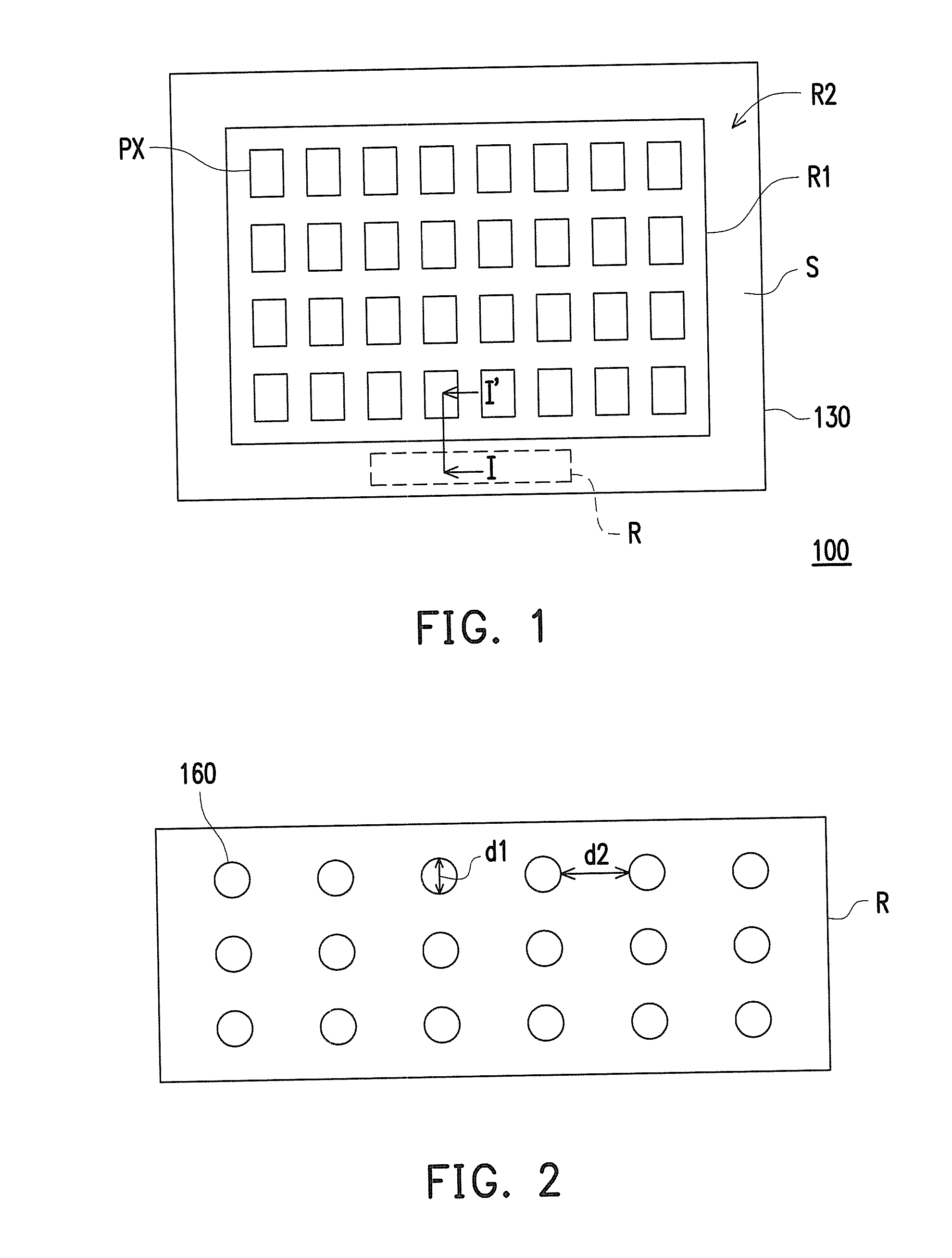
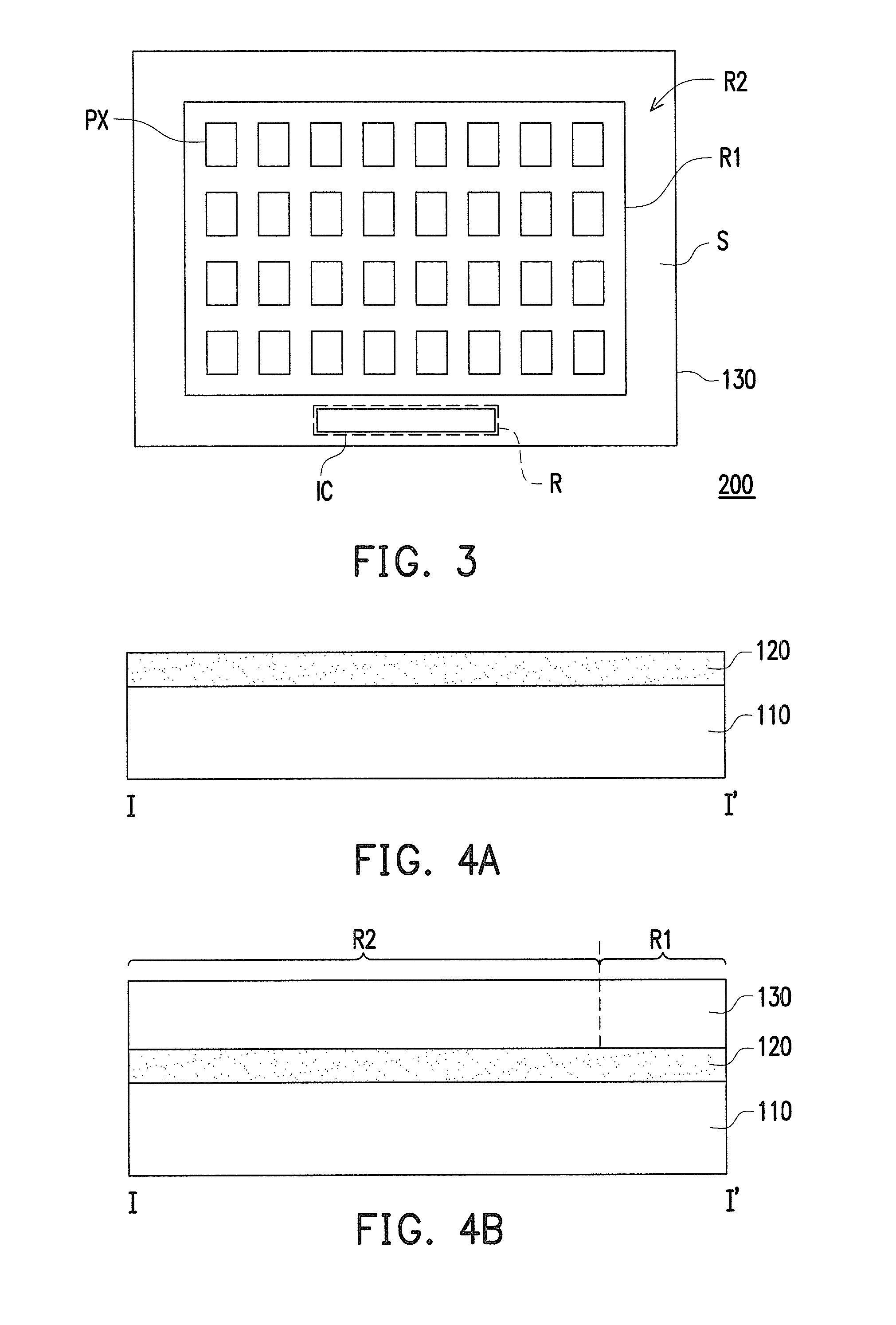
[0016]FIG. 1 illustrates a schematic top view of a display panel according to an embodiment of the invention. FIG. 2 illustrates a schematic enlarged view of an R region in the display panel of FIG. 1. Please refer to FIG. 1 and FIG. 2 simultaneously. In the present embodiment, a substrate 130 of a display panel 100 includes a display region R1 and a non-display region R2. Images are displayed in the display region R1 of the display panel 100, so that devices (such as pixel structures PX and display medium) for displaying images in the display panel are disposed in the display region R1. As shown in FIG. 1, the pixel structures PX form a pixel array in the display region R1. In contrast, the non-display region R2 does not display images, so that a peripheral circuit S and a driving chip region R are generally formed in the non-display region R2, in order to avoid affecting the appearance of the display panel 100. The peripheral circuit S and the pixel structure PX are electrically c...


PUM


Abstract

A display panel is provided. The display panel includes a substrate, a pixel array, a peripheral circuit, and a protective layer. The substrate includes a display region and a non-display region. The pixel array is located in the display region of the substrate. The peripheral circuit is located in the non-display region. The protective layer is located in the display region and the non-display region. The peripheral circuit and the pixel array are covered by the protective layer. The protective layer in the non-display region has a plurality of openings, which expose the substrate. The apertures of the openings is between 1 μm and 1 mm, and the spacing between the openings is 10 μm and 1 cm.

Description

CROSS-REFERENCE TO RELATED APPLICATION[0001]This application claims the priority benefit of Taiwan application serial no. 103102702, filed on Jan. 24, 2014. The entirety of the above-mentioned patent application is hereby incorporated by reference herein and made a part of this specification.BACKGROUND OF THE INVENTION[0002]1. Field of the Invention[0003]The invention relates to a display panel and a method for fabrication thereof, and more particularly, to a flexible display panel and a method for fabrication thereof[0004]2. Description of Related Art[0005]With the rapid advance of the display technology, the display has been gradually developed from the early cathode ray tube (CRT) display to the current flat panel display (FPD). Comparing to the FPD composed by a hard carrier plate (such as a glass substrate), the FPD composed of a flexible substrate (such as a plastic substrate) has properties such as flexibility and impact resistance. Accordingly, flexible displays of which act...

Claims


Application Information

Patent Timeline
Patent Type & Authority Applications(United States)
IPC IPC(8): H01L51/52H01L27/32H01L27/12H01L51/56
CPCH01L51/5246H01L51/56H01L2227/323H01L27/1248H01L27/1259H01L27/3244H01L27/1266H10K71/80H10K59/1201H10K2102/311H10K59/8722H10K71/00H10K50/8426H10K59/12
Inventor KE, TSUNG-YINGCHENG, KUEI-NINGLIN, CHIH-CHIEHLAN, YUNG-HSIANGLAI, YEN-HUEI
Owner AU OPTRONICS CORP
Learn More