Check patentability & draft patents in minutes with Patsnap Eureka AI!

Dual rotational stent apparatus and method for endovascular treatment of aneurysms

Inactive Publication Date: 2015-08-06
RGT UNIV OF CALIFORNIA
View PDF15 Cites 79 Cited by
  • Summary
  • Abstract
  • Description
  • Claims
  • Application Information

AI Technical Summary

Benefits of technology

The technology described in this patent allows for a stent to adjust the flow of blood through its walls for treating brain aneurysms. The stent's density can be adjusted from low to high, with high levels eliminating blood flow. Additionally, the stent's surface has a variable pattern that provides flexibility in redirecting or obstructing blood flow.

Problems solved by technology

Since all these stents are designed with a low strut density to allow placement of coils through them, it is difficult to prevent blood flow from getting into aneurysms by using these stents alone.
Moreover, there is no commercially available stent with the ability to vary the blood flow through its walls for brain aneurysm therapy.

Method used


Image

  • Dual rotational stent apparatus and method for endovascular treatment of aneurysms
  • Dual rotational stent apparatus and method for endovascular treatment of aneurysms
  • Dual rotational stent apparatus and method for endovascular treatment of aneurysms

Examples


Embodiment Construction

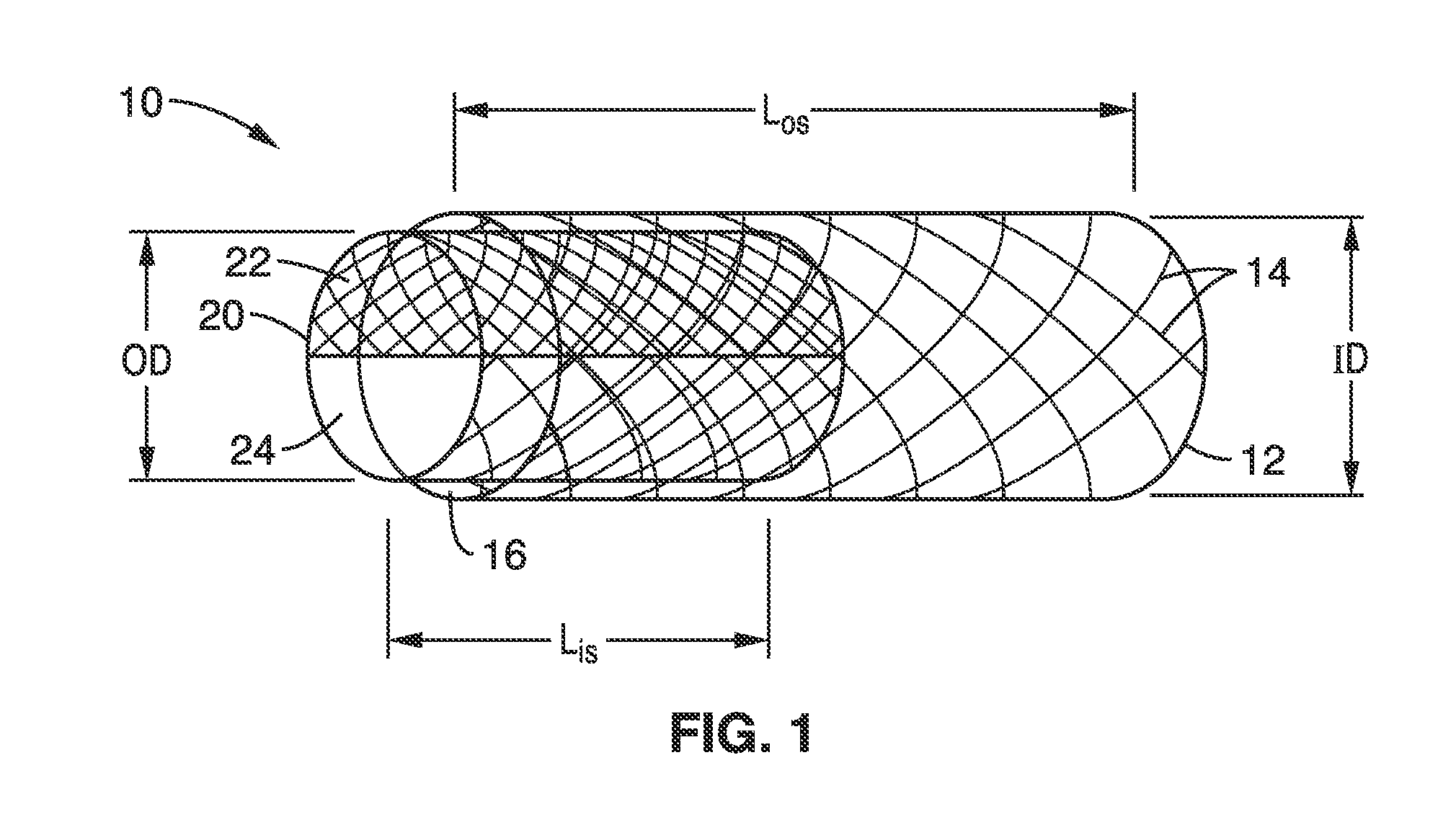
[0028]FIG. 1 shows a perspective view of compound endovascular treatment stent assembly 10 in accordance with the technology described herein. Treatment stent assembly 10 comprises two primary but separate components: an outer anchoring stent 12 and inner treatment stent 20. The inner treatment stent 20 has an outside diameter OD sized to be at or slightly smaller than the inner diameter ID or inner wall 16 of the anchoring stent 12 such that the inner treatment stent 20 may be coaxially received in and be free to slideably engage or rotate with respect to the outer anchoring stent 12.

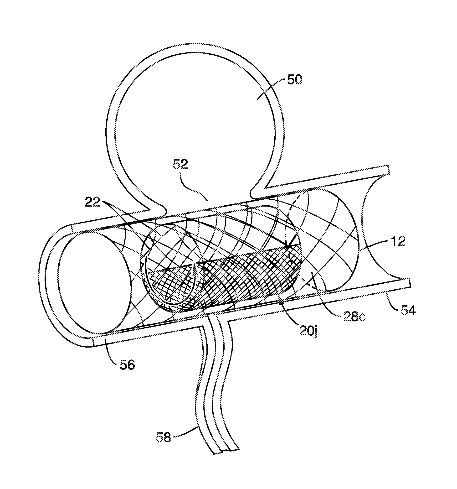
[0029]In a preferred embodiment, the components 12, 20 of treatment stent assembly 10 are configured to be delivered through a micro catheter over a guide wire (both not shown), and deployed across the neck 52 of a target aneurysm 50 (see FIG. 5).

[0030]Outer anchoring stent 12 comprises a mesh of low-density struts 14 to allow for generally unobstructed radial flow through the struts. The struts 14 are...


PUM


Abstract

A coaxial stent system is described in which an inner treatment stent is configured to be coaxially positioned inside an outer anchoring stent. The outer anchoring stent is adapted for insertion into a blood vessel and anchoring to the blood vessel at a position where the outer anchoring stent spans a neck of an aneurysm. A method for endovascular treatment of aneurysms is also described.

Description

CROSS-REFERENCE TO RELATED APPLICATIONS[0001]This application is a 35 U.S.C. §111(a) continuation of PCT international application number PCT / US2013 / 055484 filed on Aug. 17, 2013 and incorporated herein by reference in its entirety, which claims priority to, and the benefit of, U.S. provisional patent application Ser. No. 61 / 684,388 filed on Aug. 17, 2012 and incorporated herein by reference in its entirety. Priority is claimed to each of the foregoing applications.[0002]The above-referenced PCT international application was published as PCT International Publication No. WO 2014 / 028913 on Feb. 20, 2014, which publication is incorporated herein by reference in its entirety.STATEMENT REGARDING FEDERALLY SPONSORED RESEARCH OR DEVELOPMENT[0003]Not ApplicableINCORPORATION-BY-REFERENCE OF MATERIAL SUBMITTED IN A COMPUTER PROGRAM APPENDIX[0004]Not ApplicableNOTICE OF MATERIAL SUBJECT TO COPYRIGHT PROTECTION[0005]A portion of the material in this patent document is subject to copyright prot...

Claims


Application Information

Patent Timeline
IPC IPC(8): A61F2/852A61F2/848
CPCA61F2/07A61F2250/0023A61F2002/823A61F2220/0008A61F2/848A61F2/852A61F2002/826
Inventor ENZMANN, DIETERKAN, ISSEIYUKI, ICHIROVINUELA, FERNANDO
Owner RGT UNIV OF CALIFORNIA
Features
  • R&D
  • Intellectual Property
  • Life Sciences
  • Materials
  • Tech Scout
  • Unparalleled Data Quality
  • Higher Quality Content
  • 60% Fewer Hallucinations
Learn More