Light sensor system and method for processing light sensor signals

Active Publication Date: 2015-08-06
AMS AG
View PDF6 Cites 5 Cited by
  • Summary
  • Abstract
  • Description
  • Claims
  • Application Information

AI Technical Summary

Benefits of technology

[0010]The text below explains the invention in detail using exemplary embodiments with reference to the drawings. Components, signals and circuit elements that are functionally identical or have an iden

Problems solved by technology

As a consequence, the accuracy of

Method used


Image

  • Light sensor system and method for processing light sensor signals
  • Light sensor system and method for processing light sensor signals
  • Light sensor system and method for processing light sensor signals

Examples


Embodiment Construction

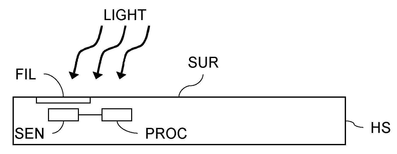
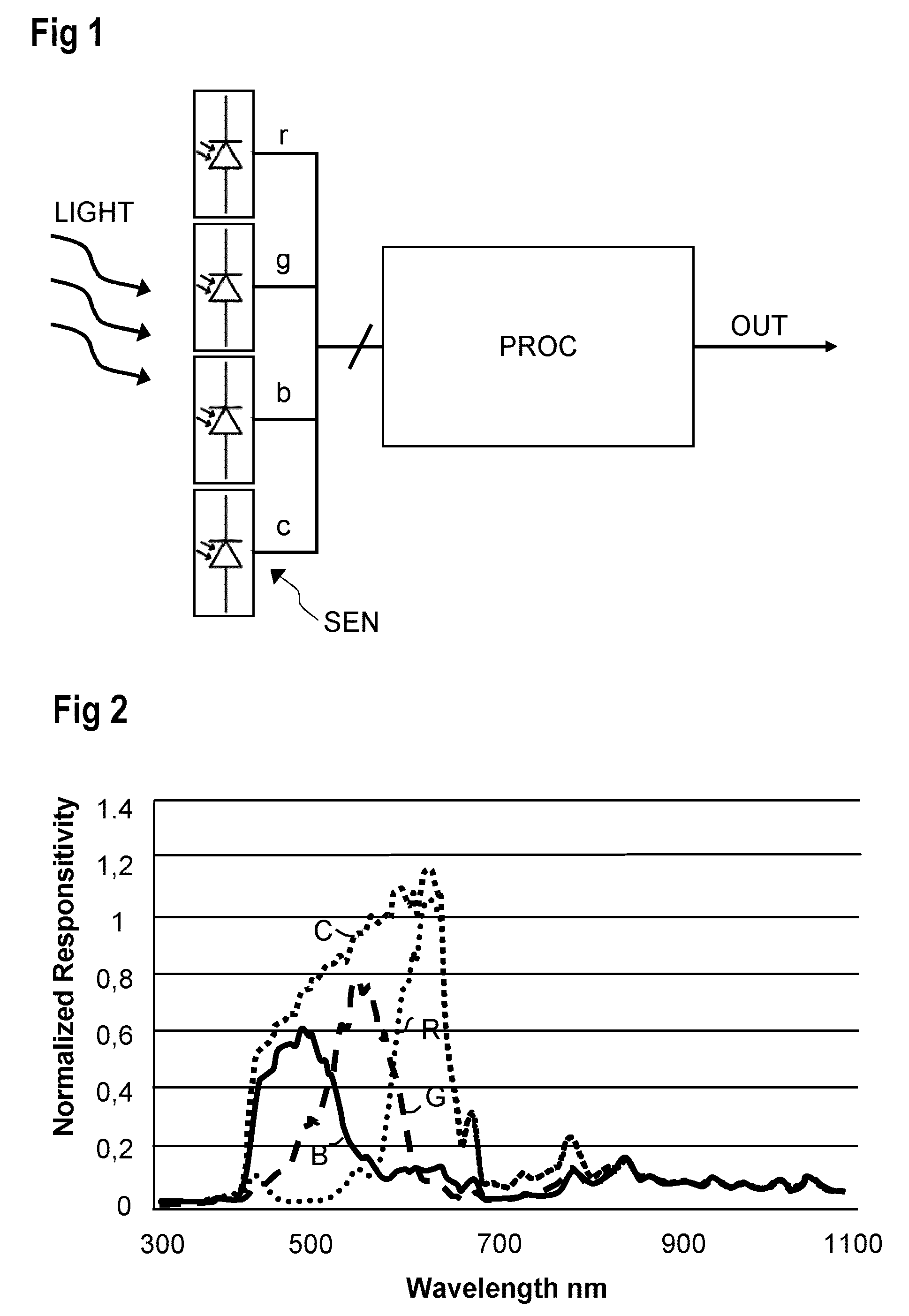
[0019]FIG. 1 shows an exemplary embodiment of a light sensor system with sensors SEN in a processing unit PROC. The sensor SEN comprises four photodiodes, to which light is provided and which are adapted to sense red light, green light, blue light and a full spectrum light in order to generate respective signals r, g, b, c provided to the processing unit PROC. The signals r, g, b, c are processed by the processing unit PROC in order to provide various output signals at an output OUT.

[0020]The sensor SEN may comprise other types of light sensors instead of the shown photodiodes. The signals r, g, b, c may be used directly by the processing unit PROC as color channel signals or are processed, for example analog-to-digital converted, to respective color channel signals, namely a red channel signal R, a green channel signal G, a blue channel signal B and a clear channel signal C.

[0021]In the embodiment of FIG. 1, one possible combination of colors and color sensors is used. However, the...


PUM


Abstract

Color light sensors are used to sense colored light and a full spectrum light in order to generate at least three color channel signals and a clear channel signal. An infrared component IR is calculated by summing up the color channel signals with individual weighting factors and subtracting a weighted clear channel signal.

Description

BACKGROUND OF THE INVENTION[0001]The invention relates to a light sensor system and to a method for processing light sensor signals.[0002]Nowadays various electronic devices comprise displays or screens that can be used under various lighting environments. To determine an actual state of the lighting environment, light sensors can be used that evaluate the intensity of the light in the visible frequency spectrum, for example. However, in conventional light sensors, not only the visible light spectrum is sensed but also an infrared component.[0003]For some applications, the infrared content is negligible and may be ignored, for example when sensing light that is emitted by an LED backlight. However, in applications that need to measure ambient light levels, the infrared component, for example of incandescent light and sunlight, may influence the intensity of light sensed by the light sensors. As a consequence, the accuracy of the measurement may be impaired. To this end, attempts are...

Claims


Application Information

Patent Timeline
IPC IPC(8): G01J1/44G01J5/60G01J1/02
CPCG01J5/60G01J1/4228G01J2001/446G01J1/44G01J1/0238G01J2001/4247G01J3/513G01J1/0492G01J3/505H01L27/14645
Inventor GLOVER, KERRYMEHRL, DAVIDJACOBS, DAN
Owner AMS AG
Why Eureka
Try Eureka