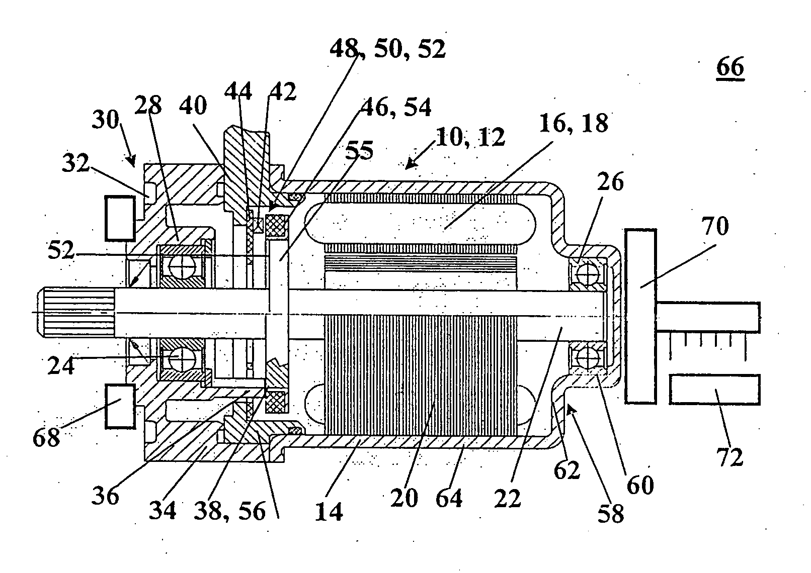
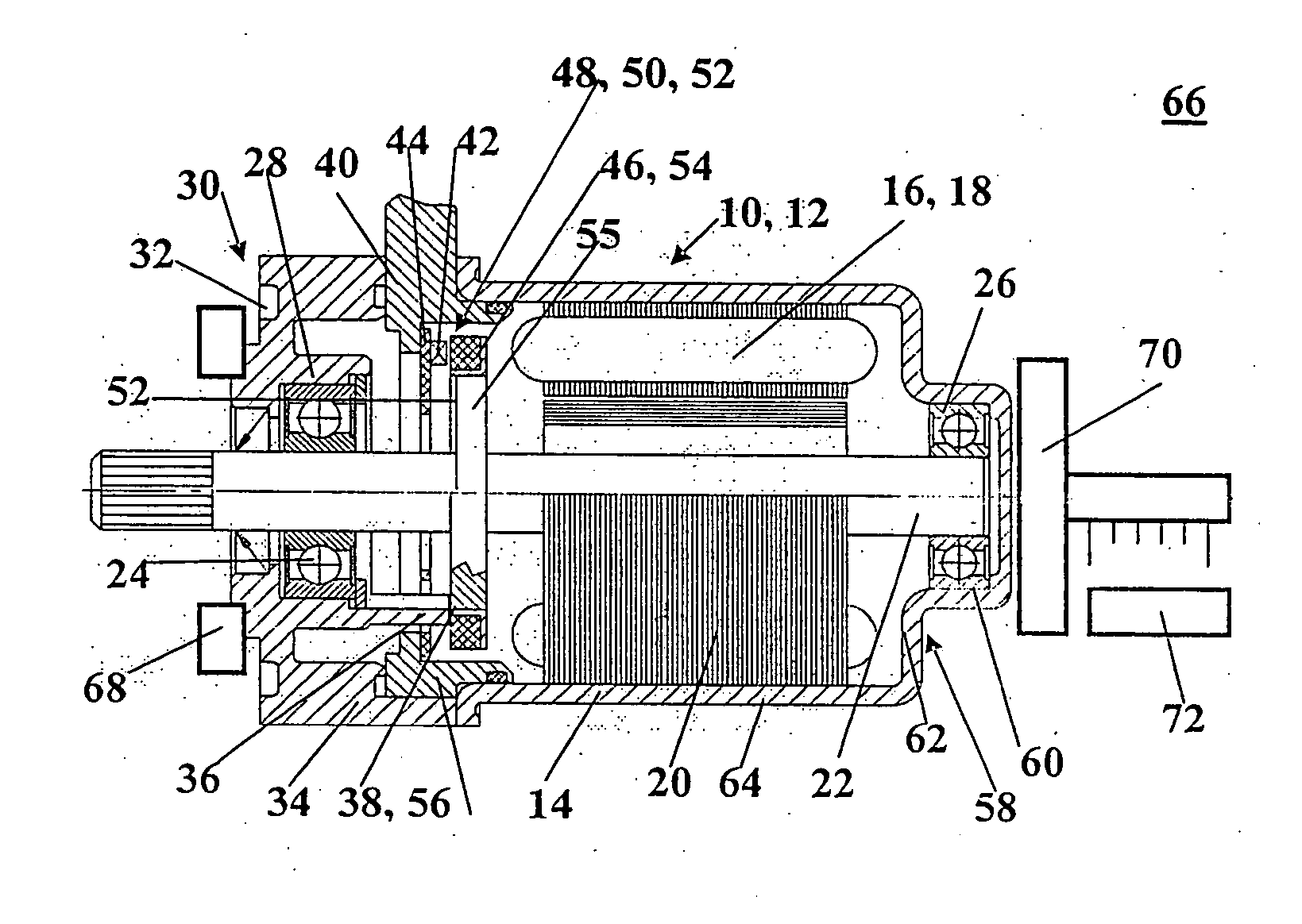
[0005] To that end, an electrical machine, including at least one sensor, a transducer wheel at which the sensor axially picks up a
signal, and an end face of the sensor is adjacent to an annular face on one face end of the transducer wheel, a shaft, on which the transducer wheel is secured, a fixed bearing and a loose bearing, in which bearings the shaft is supported, and a housing, and the transducer wheel is axially displaceable on the shaft; at least one stop is provided on the electrical machine and has at least one stop face that points in the direction of the fixed bearing; the transducer wheel likewise has at least one stop face; the stop face of the stop and the stop face of the transducer wheel are oriented toward one another and axially face one another; and the stop face of the stop is aligned axially in the direction of the fixed bearing with the end face of the sensor or protrudes past the end face of the sensor.
[0006] This leads to an increased signal precision of the
sensor system and as a result to a
narrow range of deviation in the power behavior of EC motors and EC generators. It makes it possible to produce components whose dimensional requirements can be less stringent than before, since a dimensional correction is possible during
assembly. Moreover, simple
assembly processes are the result. Provisions for achieving the function of this invention can easily be incorporated into the construction.
[0007] The axial play can be most simply adjusted if the housing has an at least axially elastically deformable region, by way of which the fixed bearing is displaceable with the shaft in the direction of the loose bearing, so that the transducer wheel can be pressed by the stop in the direction of the fixed bearing.
[0013] This can furthermore be accomplished if the loose bearing is mounted in a
flange and the sensor is mounted in an electrical subassembly; the electrical subassembly is secured to the
flange, so that a first preassembled subassembly is formed; the shaft with the transducer wheel is inserted into the housing, so that a second preassembled subassembly is formed; the two preassembled subassemblies are joined to one another; and in the
assembly process the transducer wheel rests on the stop.
[0009] To attain the axially elastic region, the housing is preferably embodied as cup-shaped; the fixed bearing is disposed in the bottom; and the bottom is axially elastically deformable, at least in a disklike region around the fixed bearing.
[0010] For the later assembly, it is simplest if the sensor is disposed on an electrical subassembly, which is disposed between the bearings.
[0011] A drive unit, in particular for a motor vehicle, such as a steering drive mechanism, power window control, sliding roof drive, drive
train pan, or the like, that has such an electrical machine has the further
advantage that the power deviation resulting from the assembly process is reduced, and tolerances in the coils, the magnetic
remanence, the sensor sensitivity itself, and so forth, are not correctable.
[0012] A simple method for adjusting the axial spacing of the electrical machine is obtained by providing that the electrical machine is retained; that a force is exerted on an at least axially elastically deformable region of the housing, so that the fixed bearing with the shaft is displaced in the direction of the loose bearing and the transducer wheel is pressed by at least one stop in the direction of the fixed bearing; and that the force is then withdrawn, as a result of which the axial spacing between the sensor and the transducer wheel is established.
[0013] This can furthermore be accomplished if the loose bearing is mounted in a
flange and the sensor is mounted in an electrical subassembly; the electrical subassembly is secured to the flange, so that a first preassembled subassembly is formed; the shaft with the transducer wheel is inserted into the housing, so that a second preassembled subassembly is formed; the two preassembled subassemblies are joined to one another; and in the assembly process the transducer wheel rests on the stop.
[0014] If the deformation of the housing is displacement-controlled, then the method can easily be implemented in large-scale
mass production.
[0015] An apparatus for performing the method has a receptacle for the electrical machine, a ram which acts on the housing and exerts the force, and a device for measuring the displacement path of the fixed bearing.
[0016] Further advantages and advantageous refinements will become apparent from the dependent claims and the description.

