Window structure

a technology for windows and doors, applied in the field of windows, can solve the problems of difficult use of light guide plates, etc., and achieve the effects of easy maintenance, good durability, and low running costs

Inactive Publication Date: 2015-08-06
MIRAI KIKAKU
View PDF16 Cites 13 Cited by
  • Summary
  • Abstract
  • Description
  • Claims
  • Application Information

AI Technical Summary

Benefits of technology

[0040]According to the present invention, the following effects are achieved.
[0041](1) When the present window structure is installed in a window, it functions as an ordinary magic mirror in cases in which the indoor side is darker than the outdoor side like during the daytime. In cases in which an indoor space is brighter than an outdoor space like during the nighttime, the planar light emitter is made to emit light so that the entire window emits light and can be put into a state in which the inside cannot be seen from the outside. Thus, it can be ensured that scenery can be viewed from the inside during the daytime, and peeping from the outdoor side can be prevented during both daytime and nighttime.
[0042](2) An LED lamp is used instead of an ordinary light, and thus the running costs are inexpensive.
[0043](3) Since an LED lamp is used, the present window structure has good durability, is compact and light, and is easy to maintain
[0044](4) The present window structure lights up at nighttime, and thus it can be used for advertising / publicity.
[0045](5) The light emission control means of the light-emitting elements enables the window of a building to be designed with various patterns and colors.

Problems solved by technology

The principal material of a light guide plate is a resin material such as acrylic resin, and it has been difficult to use such a light guide plate as is in a main opening as a construction material due to its flammability.

Method used


Image

  • Window structure
  • Window structure
  • Window structure

Examples


first embodiment

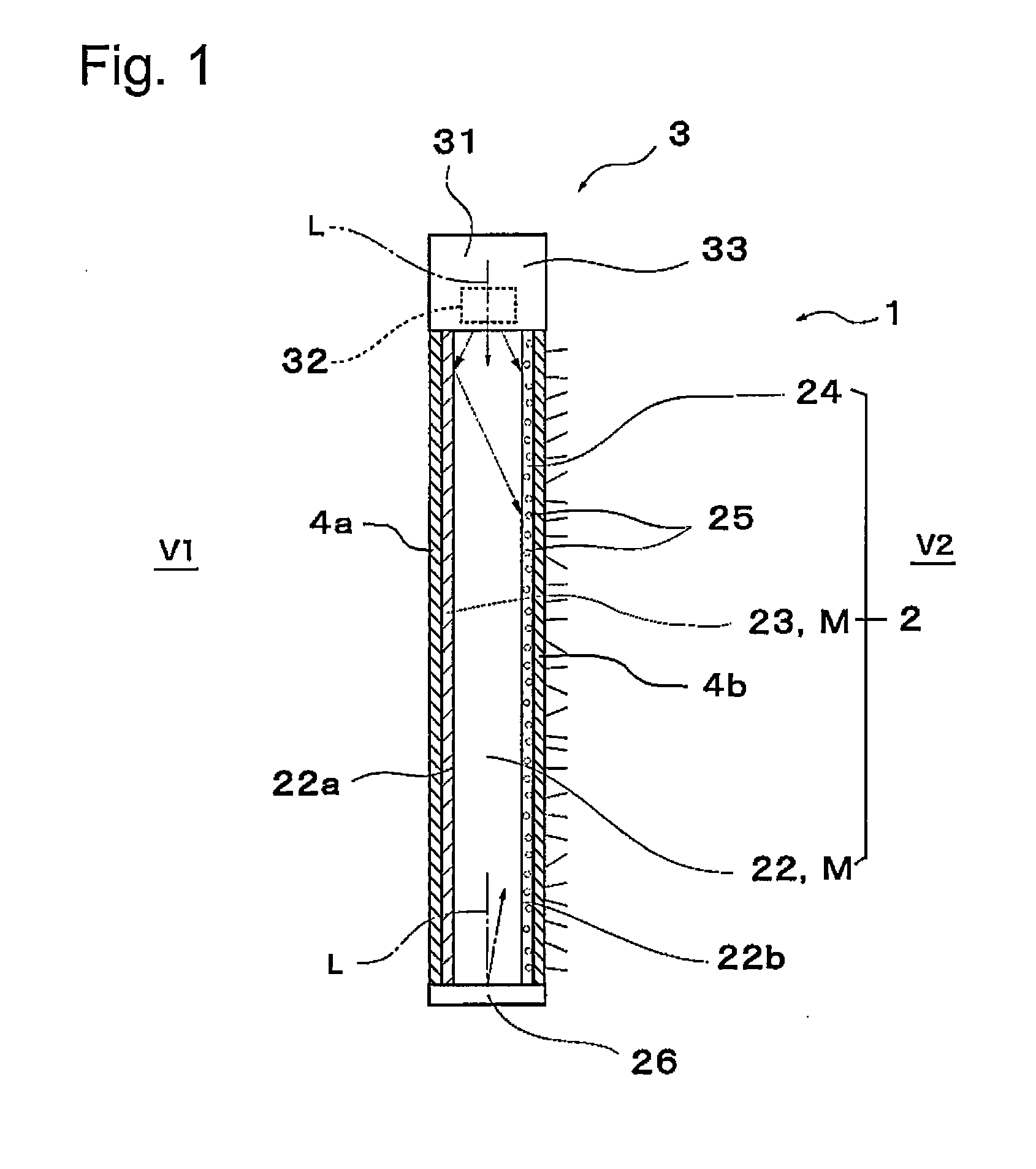
[0056]FIG. 1 is a schematic view of a window structure 1 according to the present invention when viewed in a cross-section view. The window structure 1 of the present embodiment includes a planar light emitter 2, a light-emitting device 3 thereof, and glass panels 4a and 4b that protect the inside and outside of the planar light emitter 2.

[0057]The planar light emitter 2 includes a substrate 22 made of a translucent resin panel. Although not illustrated, the substrate 22 is formed in a rectangular shape when viewed from the right or left side of FIG. 1. For the substrate 22, acrylic resin, polycarbonate, polyvinyl chloride, and the like can be used.

[0058]The substrate 22 can be colorless and transparent or colored and transparent. A thin metallic film layer 23 is laminated on a surface (V1 side) on the inside of the substrate 22.

[0059]The thin metallic film layer 23 is a thin film layer provided so as to have a predetermined light transmittance (light reflectance) by a metal having ...

second embodiment

[0080]Another embodiment of the present invention will now be explained based on FIG. 2. For convenience of explanation, this embodiment will be referred to as a second embodiment. This embodiment is related to a window structure, and is basically based on the first embodiment. Portions which are identical to those in the first embodiment will be assigned the same reference numerals, and explanations thereof will be omitted.

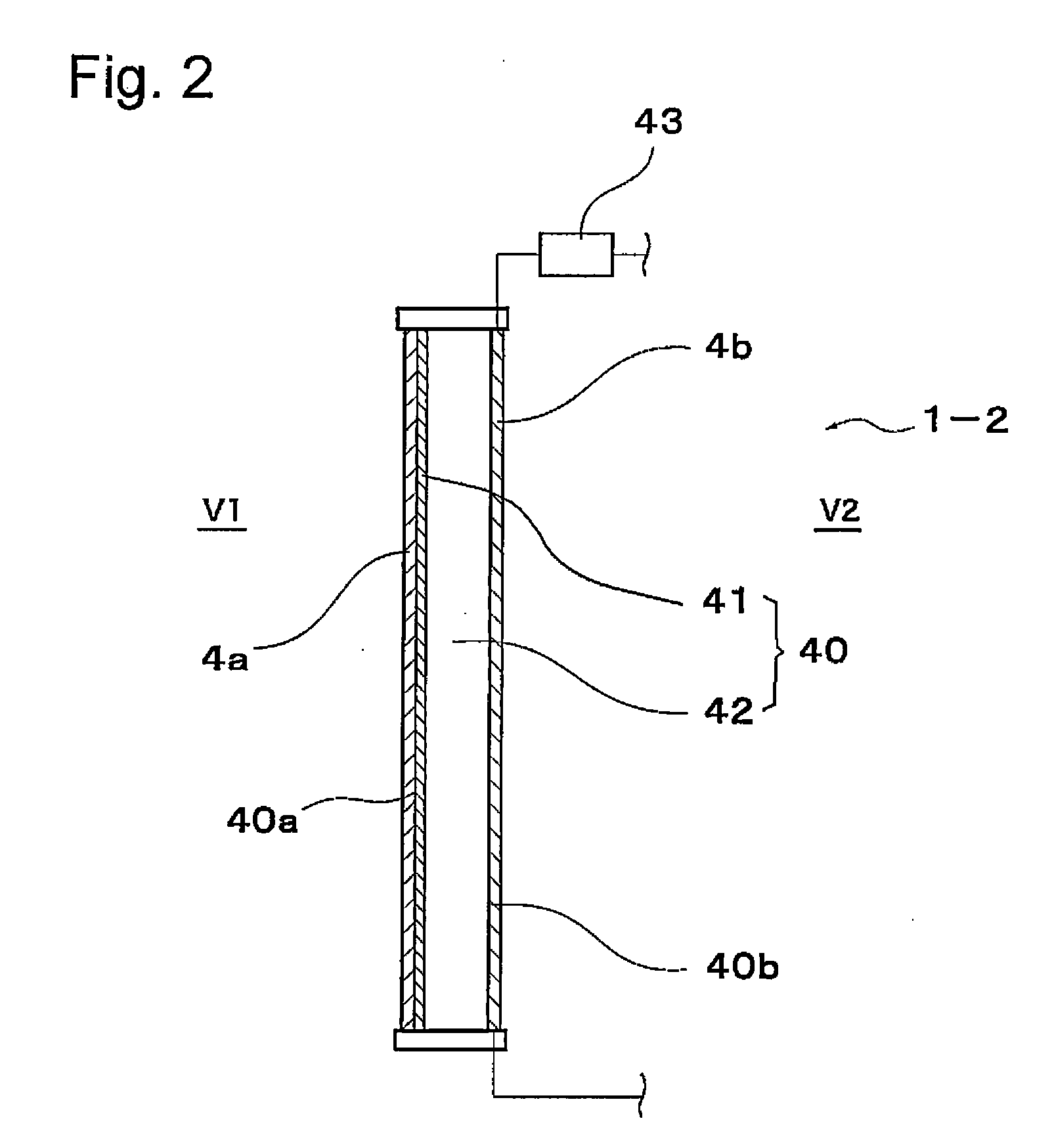
[0081]FIG. 2 is a schematic view of a window structure 1-2 when viewed in a cross-section view. The window structure 1-2 of the present embodiment includes a planar light emitter 40, and glass panels 4a and 4b that protect the inside and outside of the planar light emitter 40.

[0082]The planar light emitter 40 includes a transparent organic EL illumination panel 42 to which a thin metallic film layer 41 is laminated on the inner surface side (V1 side) thereof, and a control circuit 43. The control circuit 43 controls the voltage that is applied to the organic EL i...

third embodiment

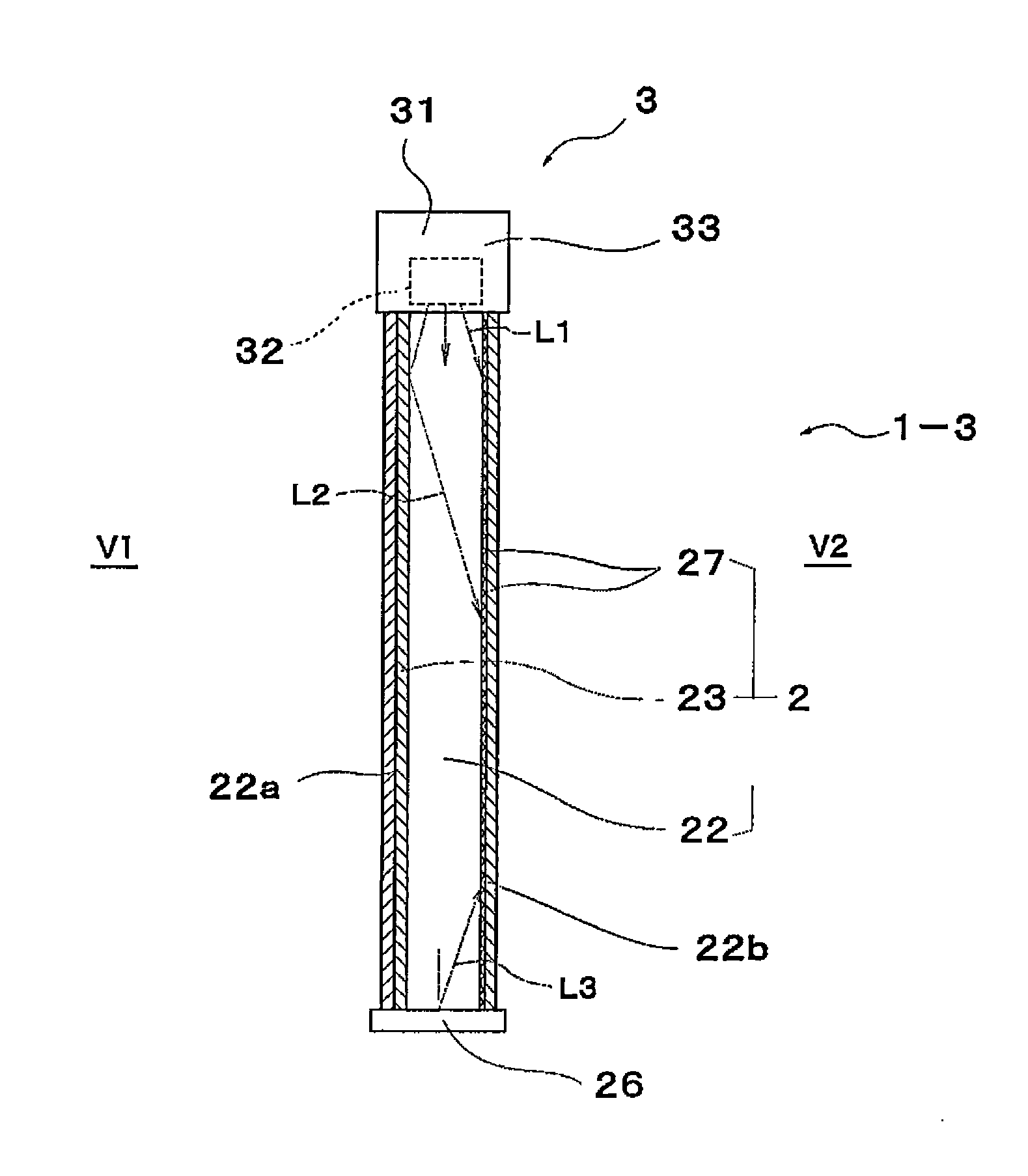
[0085]FIG. 3 is a schematic view of a window structure 1-3 when viewed in a cross-section view. The window structure 1-3 of this embodiment includes a planar light emitter 2, a light-emitting device 3 thereof, and glass panels 4a and 4b that protect the inside and outside of the planar light emitter 2.

[0086]The planar light emitter 2 includes a substrate 22 made of a translucent resin panel. A thin metallic film layer 23 is laminated on the inside (V1 side) of the substrate 22, and a diffusing part 27 is provided on the outside (V2 side) of the substrate 22.

[0087]The thin metallic film layer 23 is a thin film layer provided so as to have a predetermined light transmittance (light reflectance) by a metal having high light reflectance such as aluminum or silver.

[0088]The substrate 22 and the thin metallic film layer 23 constitute a so-called magic mirror.

[0089]The light-emitting device 3 is provided with a light-emitting part 31 and is disposed on top of the substrate 22. A bottom sur...


PUM


Abstract

To realize a window structure that can ensure that scenery can be viewed from an indoor space during the daytime and prevent peeping from outdoors regardless of whether it is daytime or nighttime.A window structure including a translucent planar light emitter in which a half mirror layer is provided on the inside thereof, and glass panels provided on an inside and an outside of the planar light emitter. The planar light emitter includes a translucent resin panel, a light-emitting element provided on an end surface of the resin panel, and a light diffusing layer provided on a surface of the translucent resin panel. A surface of the planar light emitter emits light when light of the light-emitting element enters from the end surface of the resin panel, is reflected by the half mirror layer, and is diffused by the light diffusing layer.

Description

TECHNICAL FIELD [0001]The present invention relates to a window structure that ensures that scenery can be viewed from a space inside of a building and prevents peeping from a space outside of a building.BACKGROUND ART [0002]Various conventional inventions have been disclosed in relation to a window structure using a magic mirror (a beam splitter which looks like a mirror from a bright side and looks transmissive when viewed from a dark side).[0003]As one example, Patent Literature 1 discloses providing an illumination device across the top, bottom, left and right of a window frame on the outdoor side of a transparent panel such as a half mirror that is fitted into the window frame, and providing reflectors that reflect light from the illumination device to make the illumination uniform on the indoor side. According to Patent Literature 1, the indoors cannot be seen when looking at the indoors from the outdoor side, but the scene outdoors can be seen from the indoors even at nightti...

Claims


Application Information

Patent Timeline
Patent Type & Authority Applications(United States)
IPC IPC(8): F21V8/00F21V23/00E06B9/24F21S8/02E06B7/00E06B7/28
CPCF21V33/006G02B6/0051E06B9/24G02B5/02G02B5/08G02B5/0242G02B5/0278E06B3/66E06B7/28E06B2009/2417E06B2009/247E06B7/00F21W2131/107F21V23/003F21S8/024F21Y2101/02E06B3/66376E06B3/6715F21Y2115/10
Inventor NOHARA, TSUYOSHIARIGA, SHUNJI
Owner MIRAI KIKAKU
Why Eureka
Try Eureka