
Low dead space liquid trap

a liquid trap and low-dest space technology, applied in the field of low-dest space liquid traps, can solve the problems of sample line occlusion and waveform distortion, sidestream monitoring has some drawbacks, etc., and achieves the effect of fast response time and inability to easily monitor non-intubated patients

Active Publication Date: 2015-08-13
KONINKLIJKE PHILIPS ELECTRONICS NV
View PDF8 Cites 3 Cited by
  • Summary
  • Abstract
  • Description
  • Claims
  • Application Information

AI Technical Summary

Benefits of technology

The patent text is about a technology called capnography that measures a patient's breathing and can quickly show if their condition is getting worse or better. This helps emergency medical professionals make important decisions about whether to intubate a patient and monitor their blood gas levels. The text also explains that certain devices require a secondary flow to separate liquid from gas samples.

Problems solved by technology

A misplaced tube in the esophagus can lead to death.
However, in general mainstream monitoring has some drawbacks.
Such drawbacks include the inability to monitor non-intubated patients easily.
In general, sidestream monitoring has some drawbacks in comparison to mainstream monitoring, including for example sample line occlusion and waveform distortions.
This decrease in water vapor pressure can cause an apparent increase in CO2 concentration.
One of the primary challenges in sidestream monitoring is separating any condensed liquid (e.g., water) from the gas sample and preventing the liquid from entering the gas monitoring device where it can damage the sensor.
Unfortunately, the commonly available water traps have too much dead space and volume, and the resulting impact on the gas sample characteristics is detrimental to the system performance.
In particular, the gas measurement accuracy, respiratory rate range, and signal fidelity are all negatively impacted by a large dead space in a water trap in a sidestream capnography system.
Furthermore, the need for a large breath sample rate has inhibited use of sidestream monitoring in low-flow applications.

Method used


Image

  • Low dead space liquid trap
  • Low dead space liquid trap
  • Low dead space liquid trap

Examples


Embodiment Construction

[0041]The present invention will now be described more fully hereinafter with reference to the accompanying drawings, in which preferred embodiments of the invention are shown. This invention may, however, be embodied in different forms and should not be construed as limited to the embodiments set forth herein. Rather, these embodiments are provided as teaching examples of the invention.

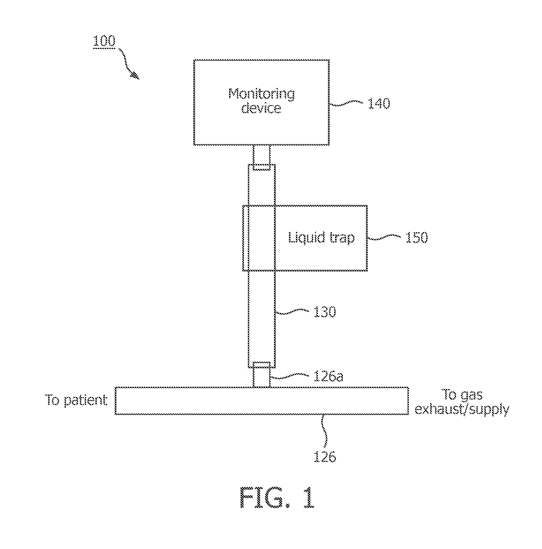
[0042]FIG. 1 illustrates one example embodiment of an arrangement 100 which employs sidestream monitoring of a patient's respiratory gas. Arrangement 100 include a breathing tube 126 through which passes the respiratory gas of a patient. Tube 126 has a monitor port 126a which is connected via a tube 130 and a liquid trap 150 to a monitoring device 140.

[0043]In some embodiments, monitoring device 140 may comprise a capnography monitor. In particular, monitoring device 140 may include a sensor for measuring the CO2 concentration in a gas sample, and a display for displaying the CO2 concentration versus...


PUM


Abstract

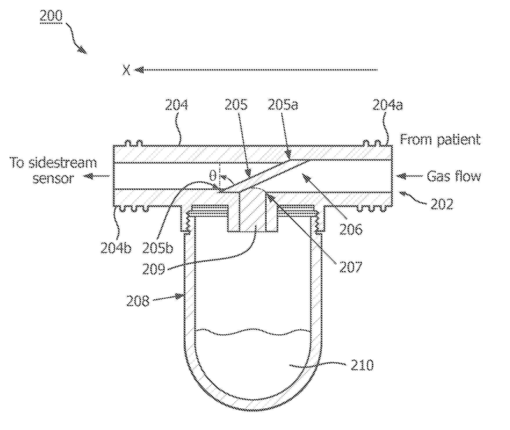
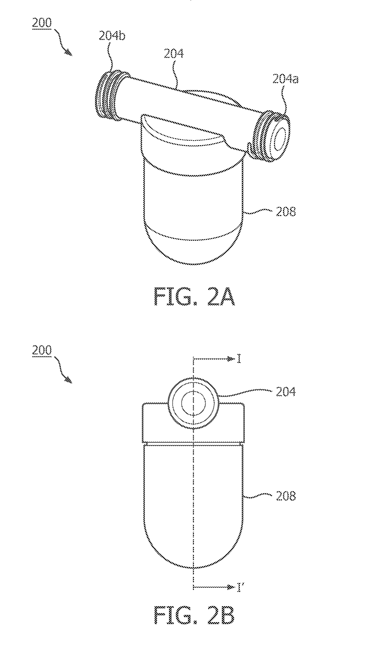
A low dead space liquid trap includes: a tube, having an inlet, an outlet, and an aperture disposed between the inlet and the outlet at a bottom of the tube, wherein the tube defines a channel extending in a first direction between the inlet and the outlet, the channel having a cross section perpendicular to the first direction; a reservoir disposed beneath the aperture of the tube; and a gas permeable membrane extending across the channel at an angle greater than zero with respect to the cross section of the channel.

Description

TECHNICAL FIELD[0001]This invention pertains to a low dead space liquid trap, for example a liquid trap that may be employed in a sidestream monitoring arrangement which measures one or more characteristics of a patient's respiratory gas.BACKGROUND AND SUMMARY[0002]It is often desirable to measure one or more characteristics of a patient's respiratory gas, for example a patient under ventilation or anesthesia, or connected to an external air or oxygen supply. In particular, it is often desirable to measure carbon dioxide (CO2) levels in the respiratory gas of a patient.[0003]Capnography monitors the concentration or partial pressure of CO2 in the respiratory gas of a patient and provides a graphic display of instantaneous CO2 concentration (FCO2) versus time or expired volume during a respiratory cycle. This display may be referred to as a CO2 waveform or capnogram. Similarly, capnometry measures and displays carbon dioxide (CO2) levels on a digital or analog monitor, for example sh...

Claims


Application Information

Patent Timeline
IPC IPC(8): A61B5/08B01D53/22B01D53/14
CPCA61B5/082B01D2053/221B01D53/229B01D53/14A61M16/0833A61B5/097A61M16/0051A61M16/0808A61M16/105A61M2016/103A61M2230/432A61M2230/50A61M16/085A61M16/021
Inventor FUDGE, BRIAN MATTHEWSCAMPOLI, DAVID
Owner KONINKLIJKE PHILIPS ELECTRONICS NV
Learn More