Pressure indicator for an oscillating positive expiratory pressure device

a positive expiratory pressure and pressure indicator technology, which is applied in the field of pressure indicators for respiratory treatment devices, can solve the problems of affecting the bronchial obstruction of the lungs, splitting open obstructed airways, and insufficient single cough to clear obstructions, and achieves the effect of reducing oscillations

Active Publication Date: 2015-08-13
TRUDELL MEDICAL INT INC
View PDF5 Cites 36 Cited by
  • Summary
  • Abstract
  • Description
  • Claims
  • Application Information

AI Technical Summary

Benefits of technology

[0009]In another aspect, the pressure stabilizer orifice may have a cross-sectional area between 0.196 mm2 and 1.767 mm2. The pressure stabilizer office may have a cross-sectional area between 0.283 mm2 and 0.636 mm2. A cross-sectional area of the pressure stabilizer orifice may be less than a cross-sectional area of the conduit along an entire length of the conduit. A portion of the conduit may extend into the instrument or may form part of a passageway in the instrument which is in fluid communication with the conduit. The pressure stabilizer orifice may be positioned within the portion of the conduit extending into the instrument or may form part of the passageway in the instrument which is in fluid communication with the conduit. The pressure stabilizer orifice may be configured to dampen oscillations in the pressure transmitted from the respiratory treatment device to the instrument.

Problems solved by technology

However, for individuals suffering from more significant bronchial obstructions, such as collapsed airways, a single cough may be insufficient to clear the obstructions.
It is believed that OPEP therapy, or the oscillation of exhalation pressure at the mouth during exhalation, effectively transmits an oscillating back pressure to the lungs, thereby splitting open obstructed airways and loosening the secretions contributing to bronchial obstructions.

Method used


Image

  • Pressure indicator for an oscillating positive expiratory pressure device
  • Pressure indicator for an oscillating positive expiratory pressure device
  • Pressure indicator for an oscillating positive expiratory pressure device

Examples


embodiment

Third OPEP Embodiment

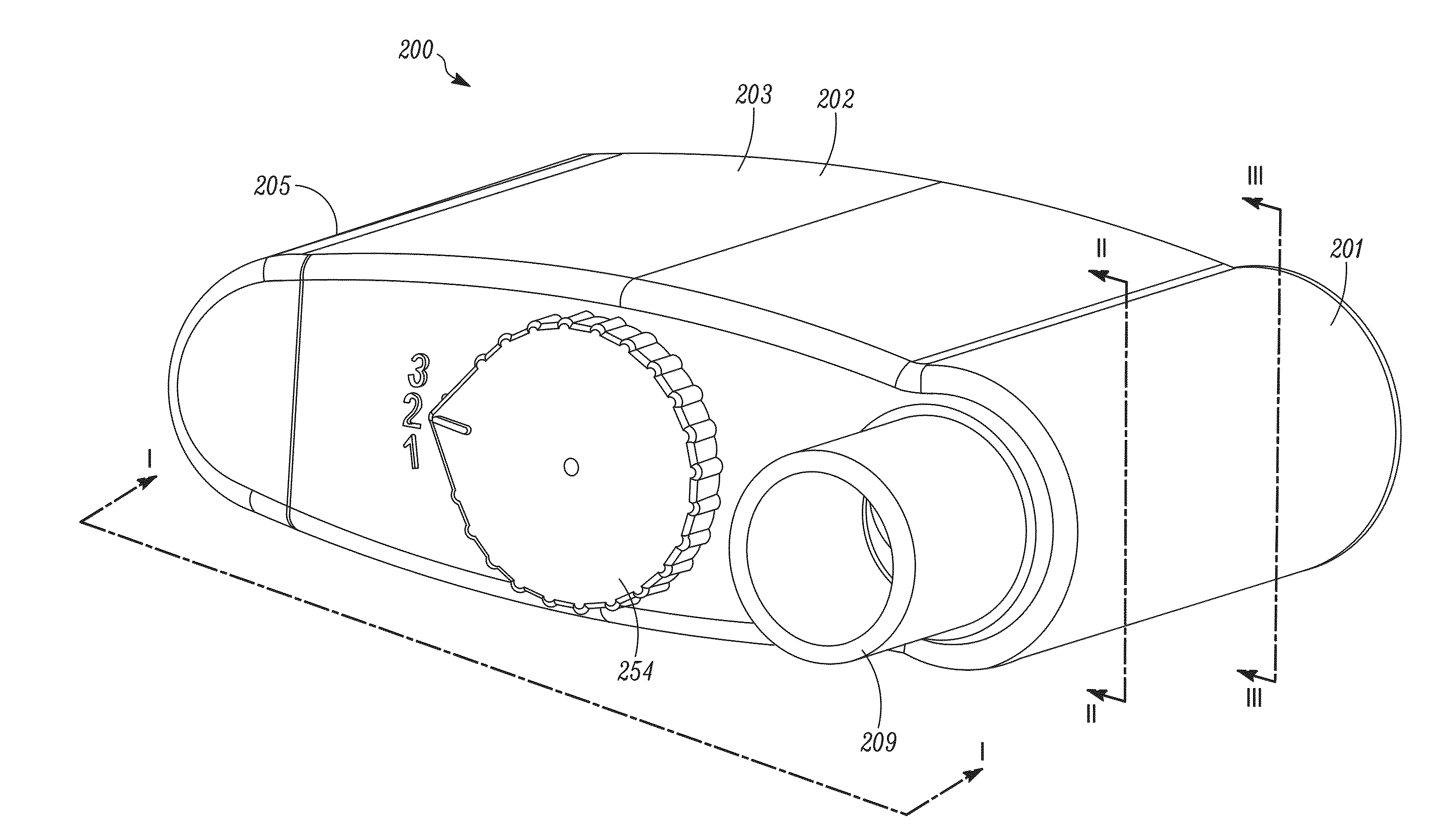
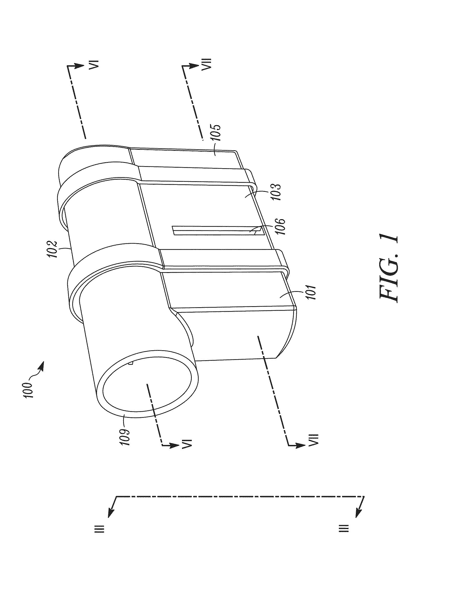
[0143]Turning to FIGS. 35-37, another embodiment of an OPEP device 300 is shown. The OPEP device 300 is similar to that of the OPEP device 200 in that is selectively adjustable. As best seen in FIGS. 35, 37, 40, and 49, the OPEP device 300, like the OPEP device 300, includes an adjustment mechanism 353 adapted to change the relative position of a chamber inlet 304 with respect to a housing 302 and a restrictor member 330, which in turn changes the range of rotation of a vane 332 operatively connected thereto. As previously explained with regards to the OPEP device 200, a user is therefore able to conveniently adjust both the frequency and the amplitude of the OPEP therapy administered by the OPEP device 300 without opening the housing 302 and disassembling the components of the OPEP device 300. The administration of OPEP therapy using the OPEP device 300 is otherwise the same as described above with regards to the OPEP device 100.

[0144]The OPEP device 300 compri...

first embodiment

of a Pressure Indicator

[0160]Turning to FIGS. 53-56, a first embodiment of a pressure indicator 400 is shown. In general, the pressure indicator 400 includes a body 402, a conduit 404 extending from the body 402, a plug 406 positioned along and inserted into the conduit 404, and an instrument for measuring pressure in the form of a manometer 408 positioned at an outlet of the conduit 404.

[0161]The body 402 may be sized and shaped for integration with existing OPEP devices, for example, as shown in FIG. 54, with the mouthpiece 309 of the OPEP device 300. In this example, the body 402 is comprised of 22 mm ISO male / female conical connectors shaped and sized to connect to the mouthpiece 309 of the OPEP device 300.

[0162]Extending from the body 402 is a conduit 404 configured to transmit a pressure from within the OPEP device 300 to the manometer 408. An inlet 405 permits a pressure within the body 402 to pass into the conduit 404. As shown, the conduit 404 extends away from the body 402...

second embodiment

of a Pressure Indicator

[0168]Turning to FIGS. 57-59, a second embodiment of a pressure indicator 500 is shown. In general, the pressure indicator 500 includes a body 502, a conduit 504 extending from the body 502, a cap 506 positioned along the conduit 504, and an instrument for measuring pressure in the form of a manometer 508 positioned at an outlet of the conduit 504.

[0169]The body 502 may be sized and shaped for integration with existing OPEP devices, for example, as shown in FIG. 58, with the mouthpiece 309 of the OPEP device 300. In this example, the body 502 is again comprised of 22 mm ISO male / female conical connectors shaped and sized to connect to the mouthpiece 309 of the OPEP device 300.

[0170]Extending from the body 502 is a conduit 504 configured to transmit a pressure from within the OPEP device 300 to the manometer 508. An inlet 505 permits a pressure within the body 502 to pass into the conduit 504. As shown, the conduit 504 extends away from the body 502 only a shor...


PUM


Abstract

A pressure indicator for a respiratory treatment device, the pressure indicator including an instrument for measuring pressures, a conduit configured to transmit a pressure within the respiratory treatment device to the instrument, and a pressure stabilizer orifice positioned within the conduit.

Description

RELATED APPLICATION[0001]This application claims the benefit of U.S. Provisional Application No. 61 / 937,433, filed Feb. 7, 2014, pending, the entirety of which is incorporated herein by reference.TECHNICAL FIELD[0002]The present disclosure relates to a pressure indicator for a respiratory treatment device, and in particular, a pressure indicator for an oscillating positive expiratory pressure (“OPEP”) device.BACKGROUND[0003]Each day, humans may produce upwards of 30 milliliters of sputum, which is a type of bronchial secretion. Normally, an effective cough is sufficient to loosen secretions and clear them from the body's airways. However, for individuals suffering from more significant bronchial obstructions, such as collapsed airways, a single cough may be insufficient to clear the obstructions.[0004]OPEP therapy represents an effective bronchial hygiene technique for the removal of bronchial secretions in the human body and is an important aspect in the treatment and continuing ca...

Claims


Application Information

Patent Timeline
Patent Type & Authority Applications(United States)
IPC IPC(8): A61M16/00A61M16/20A61M16/04
CPCA61M16/0003A61M16/049A61M16/208A61M2205/583A61M2205/3331A61M2205/581A61M2016/0027A61M2205/584A61M16/0866A61M16/0006A61M2205/3348A61M2205/3341
Inventor ALIZOTI, NERITANDOBSON, CHRISSCHMIDT, JAMES
Owner TRUDELL MEDICAL INT INC
Why Eureka
Try Eureka