Fluid ejection method and fluid ejection device

a technology of fluid ejection and fluid ejection, which is applied in the direction of fluid jet surgical cutters, medical science, surgery, etc., can solve the problems of weakened excision power per pulse, difficulty for users to select optimal fluid ejection, excess or deficiency, etc., and achieve the effect of increasing the flow rate of fluid ejection

Inactive Publication Date: 2015-08-13
SEIKO EPSON CORP
View PDF4 Cites 4 Cited by
  • Summary
  • Abstract
  • Description
  • Claims
  • Application Information

AI Technical Summary

Benefits of technology

[0017]When the fluid supply flow rate and the frequency of the volume variations are in a proportional relationship, the variations in fluid supply flow rate with respect to the frequency are expressed by a straight line having a gradient. If the displacement volume is varied, the fluid ejection flow rate varies correspondingly, so that the fluid supply flow rate may result in excess or deficiency. The variations in fluid supply flow rate can be changed by changing the gradient of the straight line according to the variations in displacement volume. The displacement volume (the excision power per pulse) can be varied while compensating the excess and deficiency of the fluid supply flow rate. Therefore, independent adjustment of the excision power per pulse and the excision speed per unit time is enabled over a wider range than Application Example 1. The user can easily set the optimal fluid ejection conditions.Application Example 4
[0019]When the fluid supply flow rate is smaller than the fluid ejection flow rate, the excision power per pulse is weakened due to the insufficient supply. If the fluid supply flow rate is larger than the fluid ejection flow rate, the quantity of supply becomes excessive, and hence the fluid flows out from a fluid ejection opening when the fluid is not being ejected, and the visibility of the operative site is lowered. If the fluid ejection flow rate ejected from the fluid ejection opening is proportional to the product of the displacement volume of the fluid discharged from the pressure chamber and the frequency of the volume variations and the coefficient of proportion is substantially close to “1”, it may be considered that the product of the displacement volume of the fluid discharged from the pressure chamber and the frequency of the volume variations corresponds to the fluid ejection flow rate to be ejected from the fluid ejection opening. The required excision power per pulse is obtained and the favorable visibility of the operative site is easily realized by equalizing the product of the displacement volume and the frequency to the fluid supply flow rate.
[0022]The fluid ejection flow rate ejected from the fluid ejection opening is proportional to the product of the displacement volume of the fluid discharged from the pressure chamber and the frequency of the volume variations. The fluid ejection flow rate and the frequency of the volume variations have a proportional relation. If the frequency of the volume variations of the pressure chamber is increased, the fluid ejection flow rate is increased correspondingly. In this application example, it is possible to cause the fluid supply flow rate from the fluid supplying unit to vary in proportion to the frequency of the volume variations. The fluid supply flow rate from the fluid supplying unit required for the fluid ejection flow rate is secured, and the excision power per pulse and the excision speed can be adjusted adequately and independently. Therefore, the user is allowed to operate the fluid ejection device easily under optimal fluid ejection conditions without preparing a huge number of combinations of parameters.

Problems solved by technology

However, it is difficult for the user to select optimal fluid ejection conditions on a case-by-case basis from among the huge number of combinations of the parameters.
If the displacement volume is varied, the fluid ejection flow rate varies correspondingly, so that the fluid supply flow rate may result in excess or deficiency.
When the fluid supply flow rate is smaller than the fluid ejection flow rate, the excision power per pulse is weakened due to the insufficient supply.

Method used


Image

  • Fluid ejection method and fluid ejection device
  • Fluid ejection method and fluid ejection device
  • Fluid ejection method and fluid ejection device

Examples


first embodiment

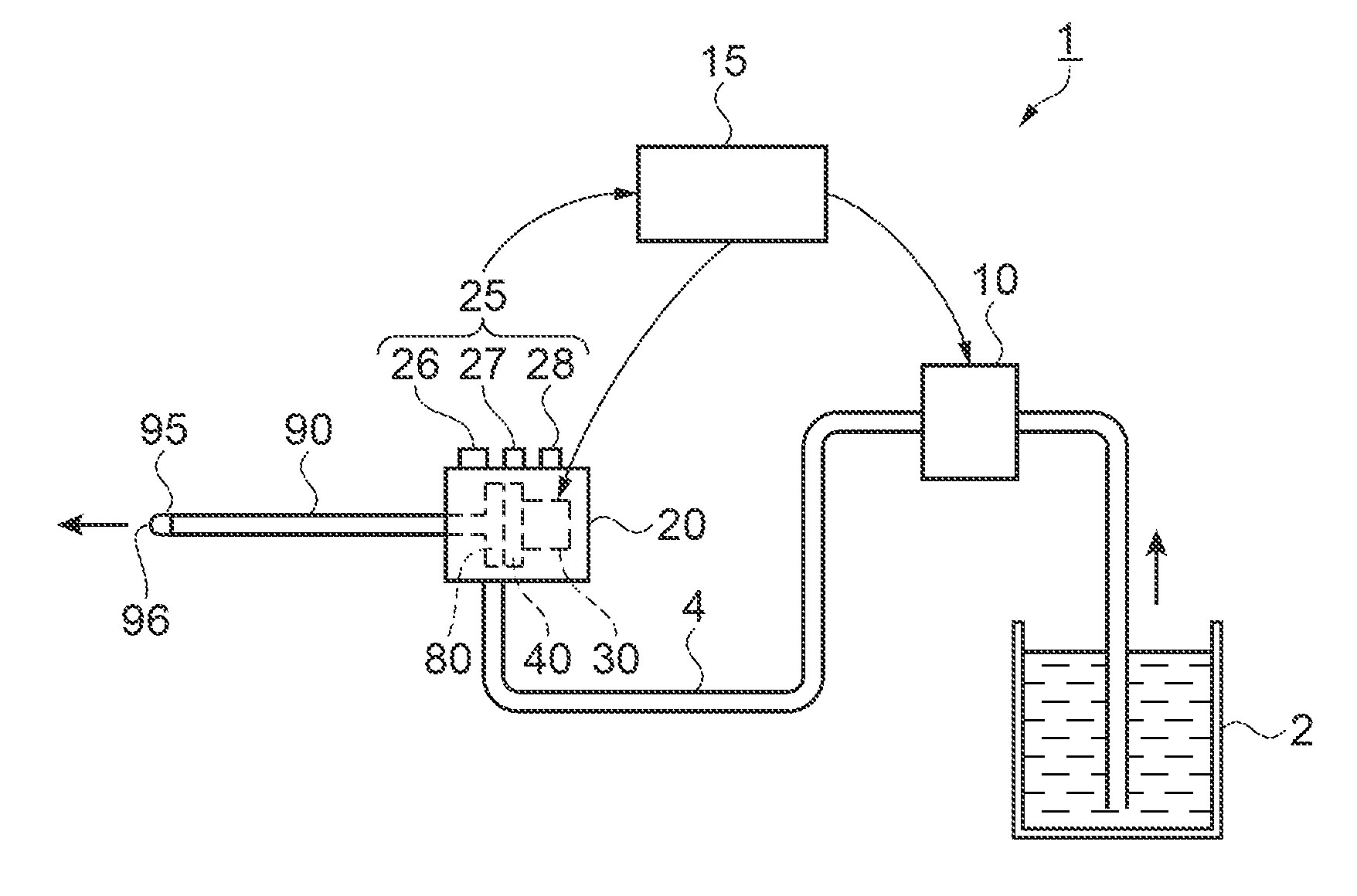
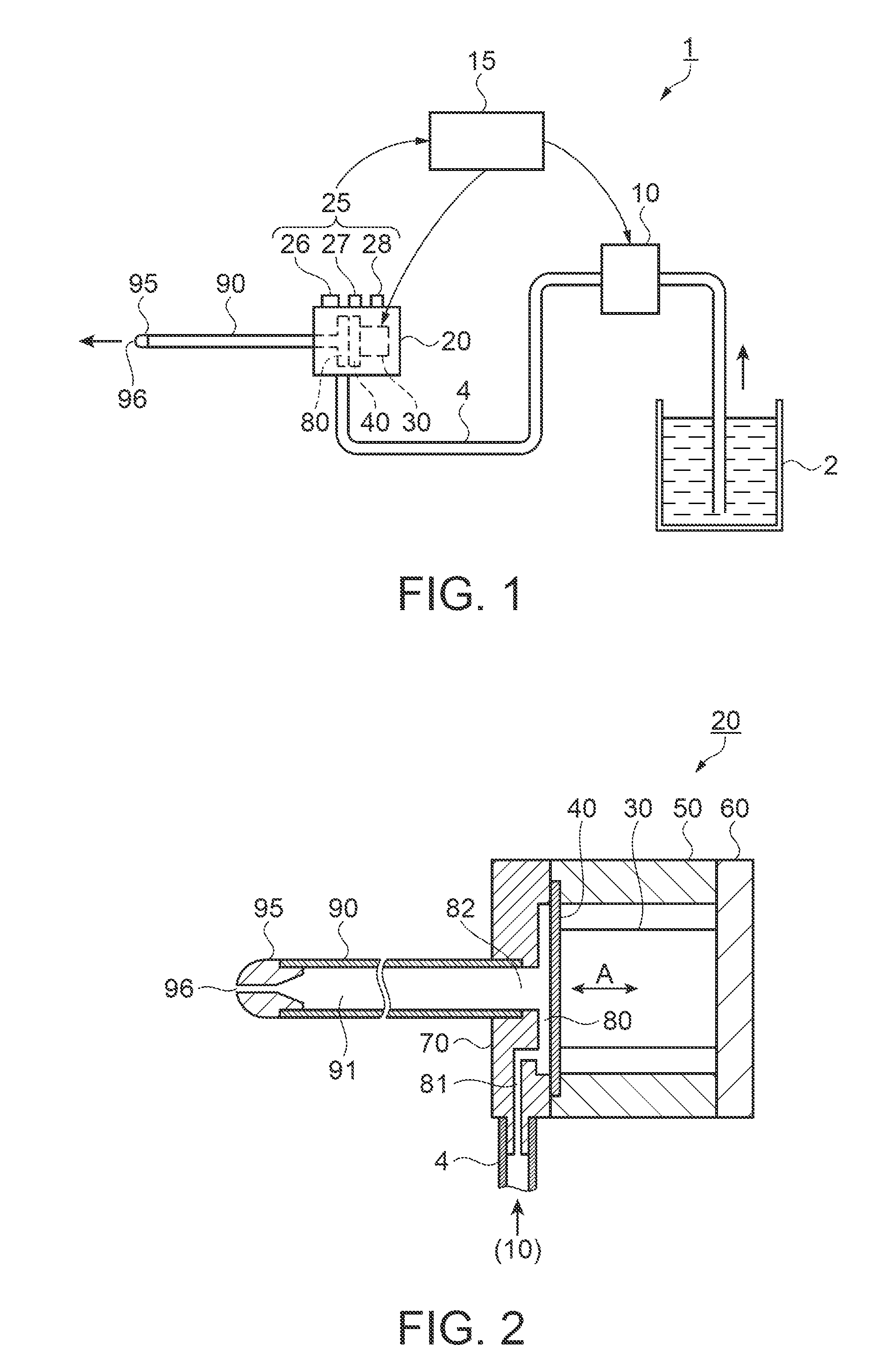
[0041]FIG. 1 is a configuration drawing showing the fluid ejection device as a surgical instrument. In FIG. 1, a fluid ejection device 1 includes a fluid supply container 2 in which fluid is stored, a pump 10 as a fluid supplying unit, a pulsed flow generator 20 as a pulsed flow generating unit configured to transform fluid supplied from the pump 10 into a pulsed flow, and a drive control unit 15 as a controller configured to control drive of the pump 10 and the pulsed flow generator 20. The pump 10 and the pulsed flow generator 20 are connected by a fluid supply tube 4.

[0042]A connecting flow channel tube 90 having a form of a thin pipe is connected to the pulsed flow generator 20. A nozzle 95 having a fluid ejection opening 96 with a reduced flow channel diameter is fixedly inserted to a distal end of the connecting flow channel tube 90.

[0043]The pulsed flow generator 20 includes a fluid ejection condition switching unit 25. The fluid ejection condition switching unit includes an ...

second embodiment

[0081]The fluid ejection method according to a second embodiment will be described. In the second embodiment, the fluid supply flow rate is varied in proportion to the displacement volume. In a description of the second embodiment, the same components as the first embodiment are designated by the same reference numerals and description thereof is omitted.

[0082]FIG. 9 is a graph schematically showing a drive waveform according to the second embodiment. FIG. 10 is a graph schematically plotting the fluid supply flow rate versus the displacement volume. The drive waveform illustrated in FIG. 9 is a rectangular wave. An increase of the frequency of the drive waveform is achieved by changing the length of the pause. Since the drive waveform is the rectangular wave, the through rate of the voltage rise does not change even though the gain of the drive voltage is changed. If the displacement volume per drive of the piezoelectric element is increased by increasing the gain of the drive volt...

third embodiment

[0091]The fluid ejection method according to a third embodiment will be described. In the third embodiment, the voltage rise time of the drive waveform of the piezoelectric element 30 with respect to the time during which the volume of the pressure chamber 80 is reduced is maintained substantially constant when varying the drive frequency. In a description of the third embodiment, the same components as the first embodiment are designated by the same reference numerals and description thereof is omitted.

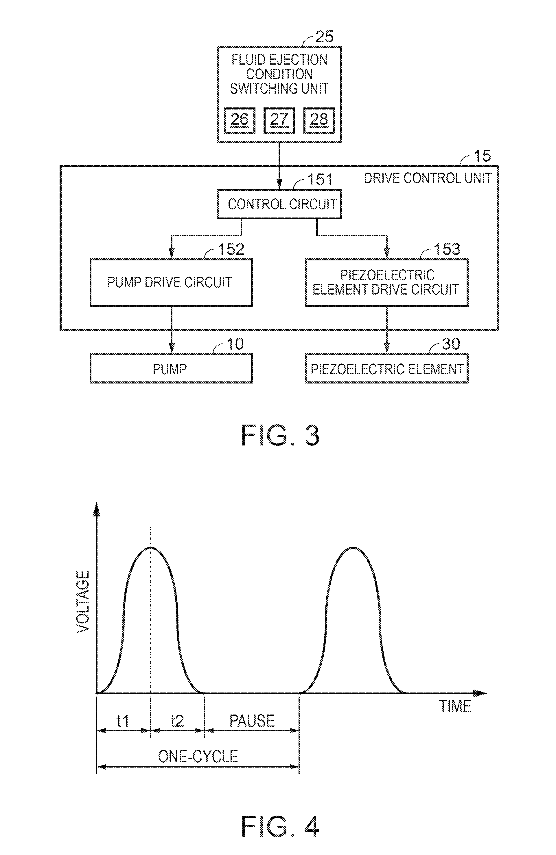
[0092]A case where the repetition frequency is lowered when a drive waveform as that shown in FIG. 4 is employed as a basic drive waveform will be described. FIG. 12 is a graph schematically showing the drive waveform when a repetition frequency is lowered. In FIG. 12, the pause is elongated, and the voltage rise time t1 of the drive waveform of the piezoelectric element 30 is not changed with respect to the time during which the volume of the pressure chamber 80 is reduced. The thro...


PUM


Abstract

A fluid ejection method includes: supplying fluid at a predetermined fluid supply flow rate to a pressure chamber; generating a pulsed flow by varying the volume of the pressure chamber at a predetermined frequency; and ejecting the pulsed flow, wherein the fluid supply flow rate is proportional to the frequency.

Description

[0001]This application is a Continuation of U.S. application Ser. No. 12 / 856,736, filed Aug. 16, 2010 which claims priority to Japanese Patent Application No. 2009-188296, filed on Aug. 17, 2009. The foregoing patent applications are incorporated herein by reference.BACKGROUND[0002]1. Technical Field[0003]The present invention relates to a fluid ejection method and a fluid ejection device for ejecting fluid in a pulsed manner.[0004]2. Related Art[0005]There are surgical instruments (fluid ejection devices) configured to incise or excise a living tissue by ejecting fluid at a high speed in a pulsed manner. The fluid ejection device includes a pulsed flow generating unit configured to transform fluid into a pulsed flow. The fluid ejection device is configured to eject the fluid at a high speed in the pulsed manner by driving the pulsed flow generating unit.[0006]The fluid ejection device includes a one-input multi-control parameter changing unit configured to change a plurality of con...

Claims


Application Information

Patent Timeline
Patent Type & Authority Applications(United States)
IPC IPC(8): B05B17/06A61B17/3203
CPCB05B17/0607A61B2017/00194A61B2017/32032A61B17/3203A61B2017/00154A61B2017/00185A61B2017/0019
Inventor KOJIMA, HIDEKISUGIMURA, SHIGEOONO, YASUHIRO
Owner SEIKO EPSON CORP
Why Eureka
Try Eureka