
Phosphor wheel and projector having the phosphor wheel

a technology of phosphor and projector, which is applied in the field of phosphor wheels, can solve the problems of reducing the optical efficiency of the phosphor layer, and burning of the gel adhering the phosphor layer on the plate, so as to achieve stable dynamic balance, reduce the temperature of the wavelength converting layer, and increase the heat dissipation area

Active Publication Date: 2015-08-13
CORETRONIC
View PDF4 Cites 28 Cited by
  • Summary
  • Abstract
  • Description
  • Claims
  • Application Information

AI Technical Summary

Benefits of technology

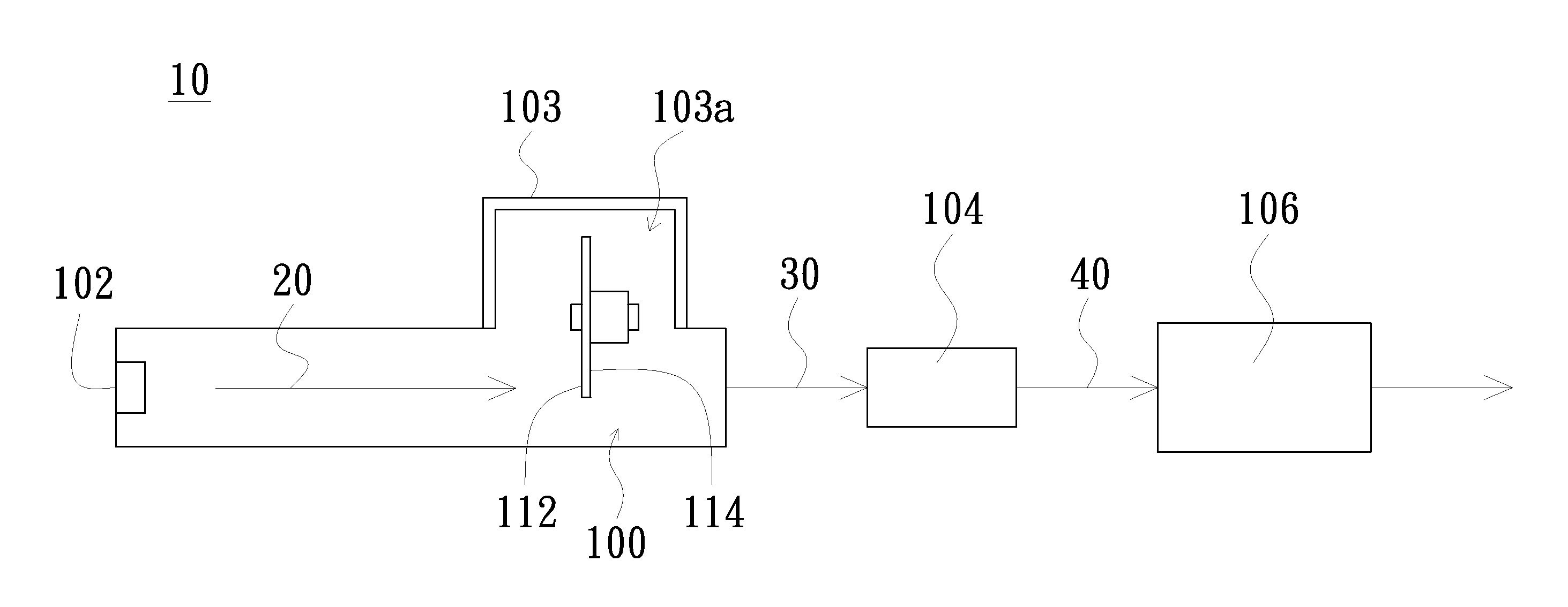
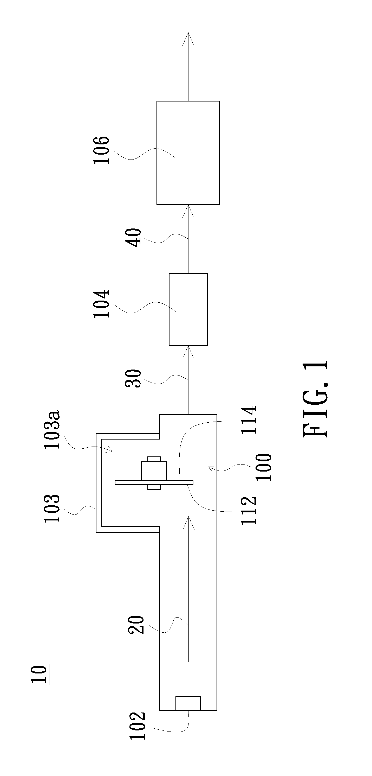
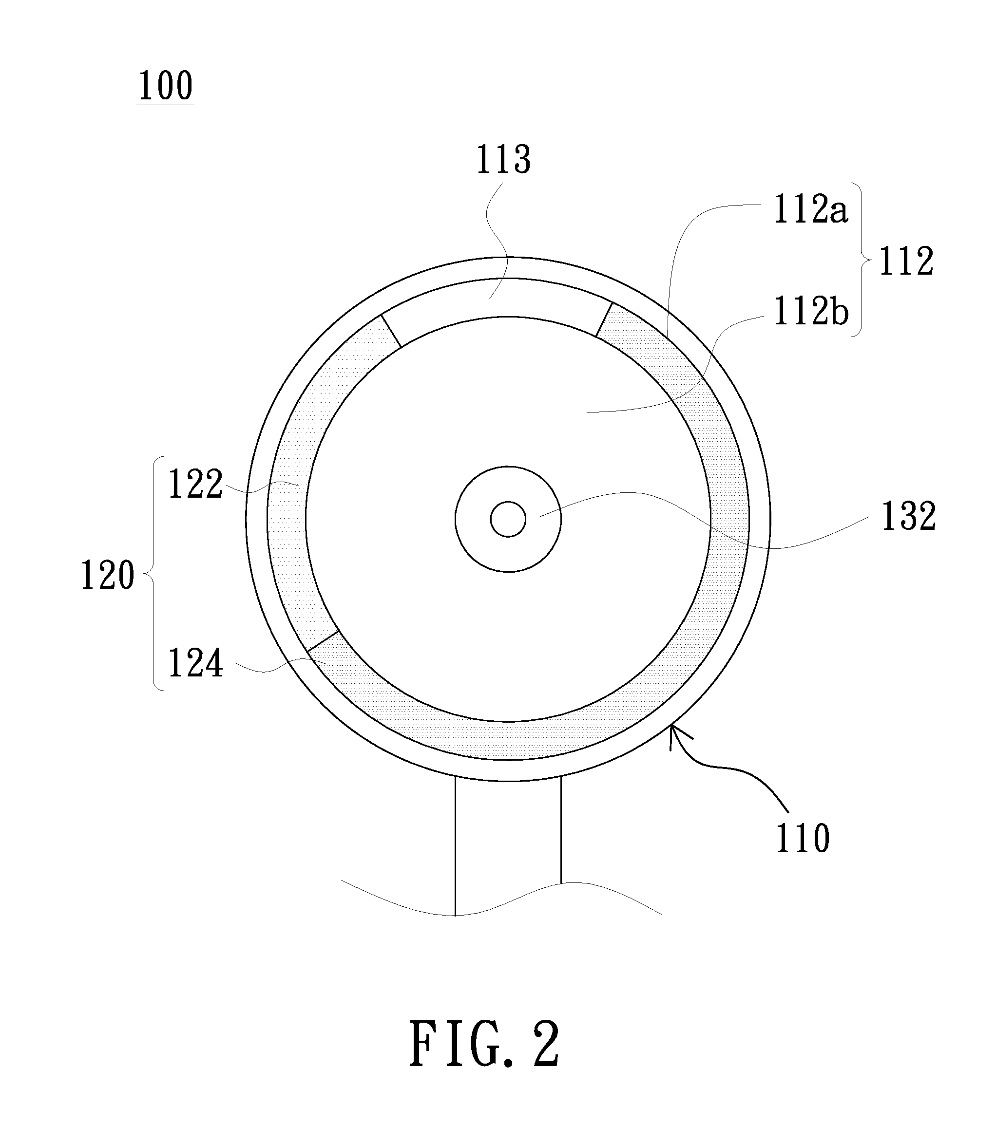
The patent describes a device that reduces the temperature of its wavelength converting layer by using a rotating disk with a recess portion. This design does not significantly change the rotating plate and ensures a stable dynamic balance when the rotating disk rotates. Additionally, the recess portion increases the heat dissipating region of the rotating disk, improving its performance.

Problems solved by technology

Simultaneously, the phosphor layer of the color wheel may be stained with the dust to cause the optical efficiency decreased.
However, owing to the needing of the high brightness, the projector has a high energy light source such that the temperature of the cavity may be increased to cause the optical efficiency of the phosphor layer being decreased and the gel for adhering the phosphor layer on the plate may be burned when the phosphor layer is disposed in an over-high temperature.
However, the mentioned patents are descript that several holes or extra structures are disposed on the plates such that the air rapidly follows to accelerate the heat dissipation of the plate, but the configuration of the plate is dramatically changed to cause the rotatable plate having an unstable dynamic balance.
Furthermore, the manufacture of the plate may need many complex processes.

Method used


Image

  • Phosphor wheel and projector having the phosphor wheel
  • Phosphor wheel and projector having the phosphor wheel
  • Phosphor wheel and projector having the phosphor wheel

Examples


Embodiment Construction

[0031]In the following detailed description of the preferred embodiments, reference is made to the accompanying drawings which form a part hereof, and in which are shown by way of illustration specific embodiments in which the invention may be practiced. In this regard, directional terminology, such as “top,”“bottom,”“front,”“back,” etc., is used with reference to the orientation of the Figure(s) being described. The components of the invention may be positioned in a number of different orientations. As such, the directional terminology is used for purposes of illustration and is in no way limiting. On the other hand, the drawings are only schematic and the sizes of components may be exaggerated for clarity. It is to be understood that other embodiments may be utilized and structural changes may be made without departing from the scope of the invention. Also, it is to be understood that the phraseology and terminology used herein are for the purpose of description and should not be ...


PUM


Abstract

A phosphor wheel includes a rotating disk and a wavelength converting layer. The rotating disk has a first surface and a second surface opposite to the first surface, in which the first surface forms a coating region and a non-coating region. The wavelength converting layer is formed on the coating region of the first surface for converting a light wavelength of a light beam. In addition, an embodiment of the invention discloses a projection device having the phosphor wheel. When the rotating disk of the phosphor wheel rotates, the recess portion may disturb the air around the phosphor wheel such that the temperature of the wavelength converting layer may be effectively decreased. Simultaneously, the rotating disk has a stable dynamic balance and the rotating disk has a larger heat dissipating region because the recess portion is disposed on the rotating disk.

Description

FIELD OF THE INVENTION[0001]The invention relates to a phosphor wheel, and more particularly to a phosphor wheel having a heat dissipating structure.BACKGROUND OF THE INVENTION[0002]The projector is a common optoelectronic display device and is widely applied in several occasions such as the life entertainment, the academic lecture, the business show. According to the principles of displaying, the projecting system includes a cathode-ray tube (CRT) display device, a liquid crystal display (LCD), a digital light processing (DLP) projecting device, and a liquid crystal on silicon (LCoS) projecting device, in which the DLP projecting device enjoys customers' high praise and shares the major market about the projecting system products because of the advantages of the DLP projecting device such as the high luminance, the high chromatic fidelity, the high response efficiency, and the compact configuration.[0003]The DLP projecting device usually has a digital micro-mirror device (DMD) to m...

Claims


Application Information

Patent Timeline
Patent Type & Authority Applications(United States)
IPC IPC(8): H04N9/31G02B26/00F21V14/08F21V9/40
CPCH04N9/3144H04N9/3114G02B26/008F21V14/08G03B21/16G03B21/204H04N9/3158
Inventor DAI, JIA-HONGHU, TUNG-CHOULIN, TSUNG-CHING
Owner CORETRONIC
Learn More