Thermal-Regulated Apparel and Wireless Control System Therefor

a technology of wireless control and clothing, applied in the direction of ohmic resistance heating, protective clothing, electrical equipment, etc., can solve the problems of wearer further typically, the wearer is difficult to quickly, easily and accurately make adjustments, and the protection clothing can also be subjected

Inactive Publication Date: 2015-08-20
GERBINGS
View PDF0 Cites 60 Cited by
  • Summary
  • Abstract
  • Description
  • Claims
  • Application Information

AI Technical Summary

Benefits of technology

[0015]The wireless heating system control application also can be provided with customizable control and / or display screens identifying and displaying the monitored temperature for each heated garment or device connected to the wireless control device, and other monitored parameters. The user can use the touch screen of their Smart Phone or other wireless device to make adjustments to the temperature of each heated garment or device separately, thus enabling them to regulate the temperature of each heated garment or device, or individual heating element assemblies thereof, being controlled as needed. The wireless heating control system also can provide for preset or optimum temperature values or ranges to be programmed, such as to conserve battery power and / or to avoid overheating.
[0021]Still further, the status of the battery or other internal power source of each heating apparatus or system also can be monitored and feedback sent to the controller, such as, through an incorporated or connected Bluetooth® communication module or functionality (i.e., the battery / power source can incorporate Bluetooth® connectivity), to a wireless control devices. i.e., the user's Smart Phone, to alert the user as to the level or amount of available battery power during use of the heated garment or device. The controller also can be configured to use other applications or features of a user's wireless device, such as retrieving the ambient temperature of the surrounding environment or weather updates through their Smart Phone, and functionality that enables the user to set a desired range or temperatures, including establishing a default temperature range for the heated garment or device if the surrounding environmental or ambient temperature is detected at a certain level or in a prescribed range, or if the detected power level or the heating apparatus power supply drops below a desired or preset level. Still further, the wireless heating control system can also be provided with other control screens and / or links to various websites, such as to retain and / or social media sets.
[0023]Often, thermistor based heating control appliances or designs will call for approximately 1% tolerance thermistors to be used. However, since there are numerous different response curves for different thermistors, the thermistor curve type also must be specified and taken into account, which can represent an additional barrier to designing apparel capable of thermal regulation. However, by utilizing a predetermined or arbitrary setpoint that is recorded when the controller unit is activated by a user, the control system on the circuitry thereof can be built using lower cost parts, or parts with a wider tolerance range. For example, instead of using expensive temperature sensors or alternatively more costly 1% precision thermistors, the control system, and related methods can be implemented using significantly lower cost thermistors, for example, approximately 10%-20% tolerance thermistors. Various alternative types of thermistors also can be used, and each thermistor used need not be identical to other thermistors, or necessarily maintain or use a known component value; this allows for substantial cost savings, as the difference between a 1% tolerance component versus a 10% tolerance component can be orders of magnitude in difference. The same can apply to the use of thermocouples.

Problems solved by technology

Additionally, such protective clothing also can be subjected to and thus must be protected from other potential problems / conditions, such as exposure to electrical surges or interference.
One problem that seems to exist, however, is that it is often difficult for the wearer to quickly, easily and accurately make adjustments to the temperature or heat being applied by the garment, if they are too hot or too cold, the wearer further typically must unzip or remove the garment to adjust the heating apparatus.
Disadvantageously, this approach typically can require multiple monitoring points, expensive equipment capable of taking such temperature measurements within a narrow error range, and often a multitude of sensors and / or other components that can potentially lead to or create numerous failure points that can hinder overall function of the heated garment.
The need for such additional temperature monitoring devices or components also can add to the overall expense, as well as the weight / bulk of a garment in which they are installed, and can otherwise affect the freedom of movement, fit and comfort of the garment.

Method used


Image

  • Thermal-Regulated Apparel and Wireless Control System Therefor
  • Thermal-Regulated Apparel and Wireless Control System Therefor
  • Thermal-Regulated Apparel and Wireless Control System Therefor

Examples


Embodiment Construction

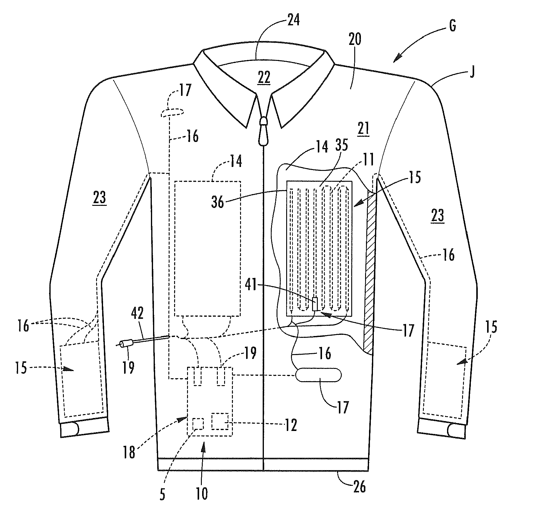
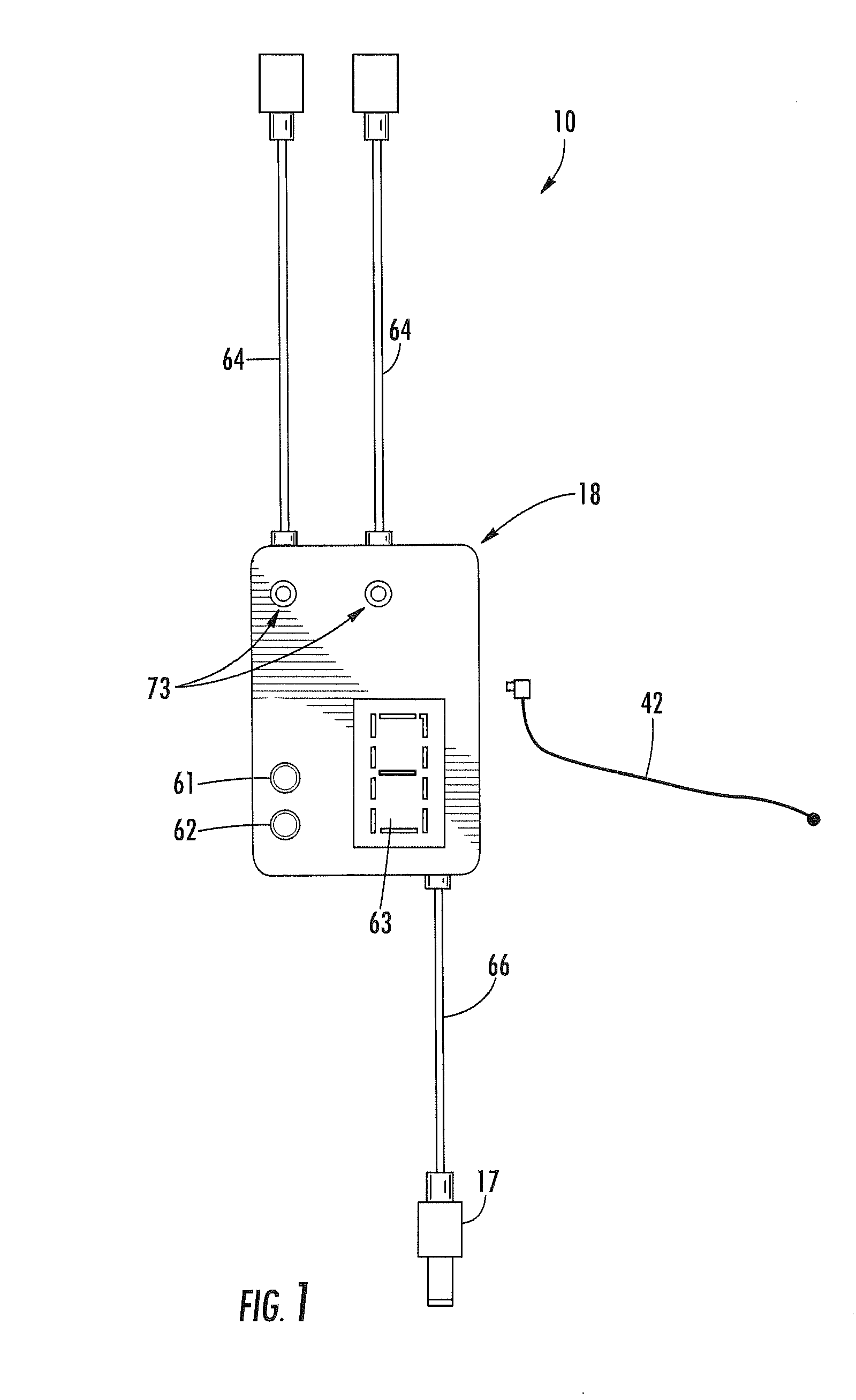
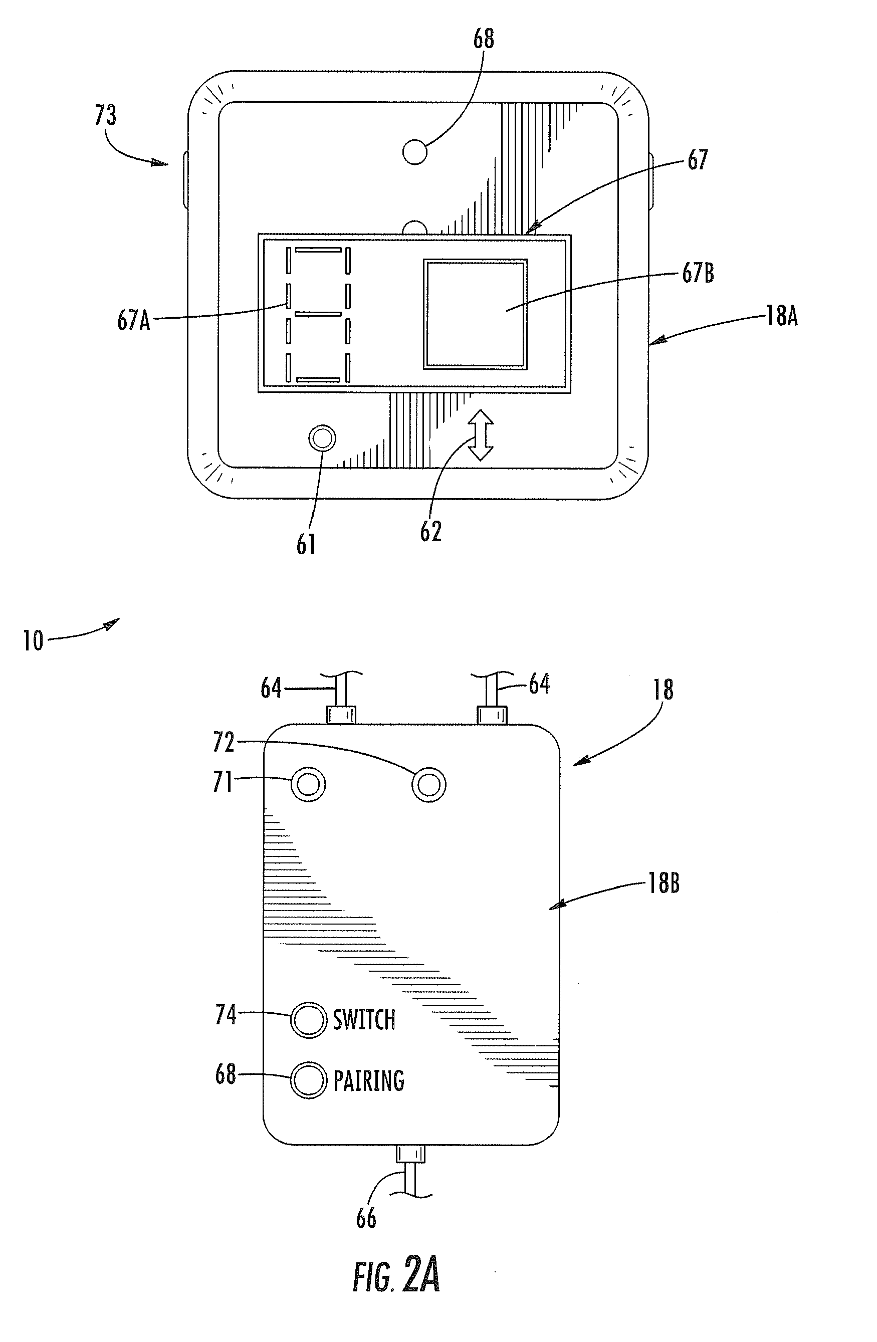
[0047]Referring now to the drawings in which like numerals indicate like parts throughout the several views, the present inventive concept shown in FIGS. 1A-11B is directed to a heating control system 10 for self-governing, thermally regulated or heated apparel / garments G (FIGS. 3A-3C and 5A-7B) and / or other articles or devices or systems (FIGS. 4A-4B) and related methods of control for such self-governing thermally regulated apparel / garments (FIGS. 8-18C). In one embodiment, thermal output or heat applied through the apparel / garment item or other article G will be controlled via the heating control system 10 through the regulation of the application of electrical power from a power source 12 to an electrically resistive heating element 11 of one or more integrated heating assemblies 15 integrated into the apparel item or garment, such as by fitting in a pocket 14 (FIG. 3A). A user, i.e., the person wearing the apparel item or garment, can engage the heating control system 10 via an...


PUM


Abstract

The present inventive concept relates to electrically-powered, thermal-regulated apparel or heated garments and a controller and related methods of operation thereof. The thermal-regulated apparel item includes a heating assembly having a heating element and a controller that is linked to the heating element. The controller receives measured temperature or other feedback such as electrical resistance values from a thermistor or a voltage level of a thermocouple positioned along the heating element and in response, varies an electrical power output to the heating element to maintain a desired thermal output. The controller also communicates with a user settable control device, which can include a wireless control device, such as a Smart phone, through which the user can monitor and control the thermal output of one or more heated garments linked thereto.

Description

CROSS-REFERENCE TO RELATED APPLICATIONS[0001]The present Patent Application is a continuation-in-part of previously filed, co-pending U.S. patent application Ser. No. 14 / 503,804, filed Oct. 1, 2014, which is a formalization of previously-filed U.S. Provisional Patent Application Ser. No. 61 / 885,166, filed Oct. 1, 2013. The present Application further is a formalization of U.S. Provisional Application Ser. No. 62 / 055,072, filed Sep. 25, 2014. This Patent Application accordingly claims the benefit of the filing date of the above-cited United States Utility and Provisional Patent Applications according to the statutes and rules governing provisional patent applications, particularly 35 U.S.C. §119(a)(3), 119(a)(4) and 37 C.F.R. §1.78(a)-(c). The specification and drawings of the United States Provisional Patent Applications referenced above are specifically incorporated herein by reference as if set forth in their entirety.FIELD OF THE INVENTION[0002]The present disclosure generally re...

Claims


Application Information

Patent Timeline
Patent Type & Authority Applications(United States)
IPC IPC(8): A41D13/005H05B1/02
CPCH05B3/34H05B2203/036H05B1/0272A41D13/0051H05B1/02
Inventor STEVENS, KAYLAROBERTS, CUPIDBASS, SPENCER
Owner GERBINGS
Why Eureka
Try Eureka