Unfortunately, however, bodily secretions (particularly those including blood or blood platelets) often form clots within medical tubes, which can partially or totally obstruct the suction pathway within the tube.
Obstruction of a medical tube can
impact its effectiveness to remove the fluid and other material for which it was originally placed, eventually rendering the medical tube partially or totally non-functional.
In some cases, a non-functional tube can have serious or potentially life-threatening consequences.
For example, if there is a blockage in a
chest tube following cardiac or pulmonary
surgery, the resulting accumulation of fluid around the heart and lungs without adequate drainage can cause serious adverse events such as pericardial
tamponade and
pneumothorax.
In addition to chest tubes used in heart,
lung, and
trauma surgery, other medical tubes are prone to clogging as well, including feeding tubes,
surgical wound drains, urinary catheters, cardiovascular catheters, and others.
There are few effective techniques to manage medical tube clogging when it occurs.
None of the above techniques is particularly effective.
Moreover, they are
time consuming and can be quite painful if the patient is awake and alert when they are performed, due to tugging on the medical tube.
Tugging on chest tubes whose terminal ends have been placed near the pleura or
pericardium can be especially painful.
In addition, the “stripping” technique is known to generate short bursts of extreme negative pressure within chest tubes, which in turn draws a strong suction in the
body cavity where its terminal end has been placed.
This can be quite dangerous in certain circumstances.
For example, negative pressures of magnitude greater than −300 cm of water can be generated adjacent suture lines on coronary
anastomosis, etc., which can disrupt some of the work that was done during a prior
surgery.
As a result, many surgeons have banned stripping their patients' chest tubes due to the potential for complications.
When the above techniques fail to clear a potentially dangerous clot within the tube, a more invasive technique must be used.
But it is highly undesirable for a number of reasons.
Breaking the seal on this
system causes loss of the normal physiologic negative pressure inside the chest.
This can result in
lung collapse (
pneumothorax) while suctioning the chest tube.
Additionally, the
suction catheter can easily be passed beyond the end of the chest tube, which has the potential to injure the heart or lungs, which could be life threatening.
Finally, this procedure is
time consuming and usually can only be performed by physicians due to the associated dangers.
Thus it is only occasionally done in extreme situations when a clogged chest tube is causing a serious acute problem.
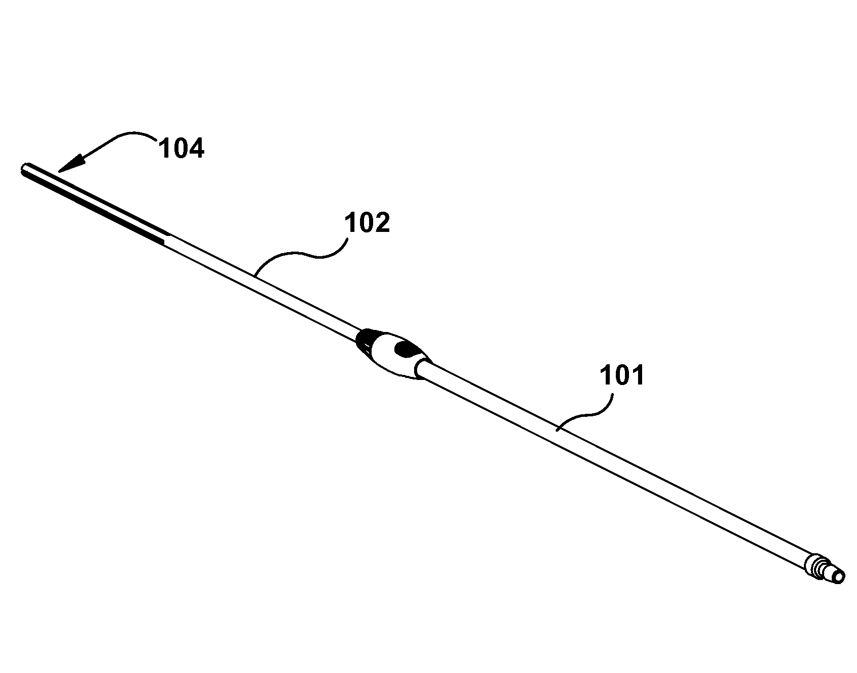
Partitioned medical tubes present a challenge for clearing obstructions from within the partitioned portion of the medical tube because a clearance apparatus may not be able to sufficiently clear each lumen of the medical tube or its partitioned portion.
When a clearance apparatus is inserted into the medical tube from its proximal end, the clearance apparatus may not be able to navigate into each separate lumen, which can result in a clot or occluding material remaining in one or more of the lumens, thus decreasing the drainage capacity of the medical tube.
Extension of the adjustable-length
guide tube results in withdrawal of the guide member relative to the medical tube, and collapse (i.e. contraction) of the adjustable-length
guide tube results in advancement of the guide member relative to the medical tube.

