Rubber extrusion device

a technology of extrusion device and rubber, which is applied in the direction of tyres, other domestic articles, domestic applications, etc., can solve the problems of large plane space and further space, and achieve the effect of saving spa

Inactive Publication Date: 2015-08-20
SUMITOMO RUBBER IND LTD
View PDF2 Cites 0 Cited by
  • Summary
  • Abstract
  • Description
  • Claims
  • Application Information

AI Technical Summary

Benefits of technology

The present invention is a rubber extrusion device that includes a rubber extruder and a gear pump connected to the discharging port of the rubber extruder. The device effectively utilizes the space below the cylinder portion or the gear pump main body, making it possible to miniaturize the device. The output shaft of the reducer is linked to one of the gears using a wrapping transmission means, ensuring proper gear pump driving. The technical effects of the invention include space saving and efficient device design.

Problems solved by technology

Unfortunately, since the conventional rubber extrusion device (b) includes three parallel axes, i.e. a rotating shaft of the electric motor (f), an output shaft of the reducer (g), and rotating axes of gears, the electric motor (f) and the reducer (g) have to be arranged laterally outside the gear pump rain body (h).
Thus, to install the rubber extrusion device on the floor, a large plane space is necessary.
In particular, as shown in FIG. 7, when two rubber extrusion devices (b) are arranged in parallel one another, there is a problem that further larger space is necessary.

Method used


Image

  • Rubber extrusion device
  • Rubber extrusion device
  • Rubber extrusion device

Examples


Embodiment Construction

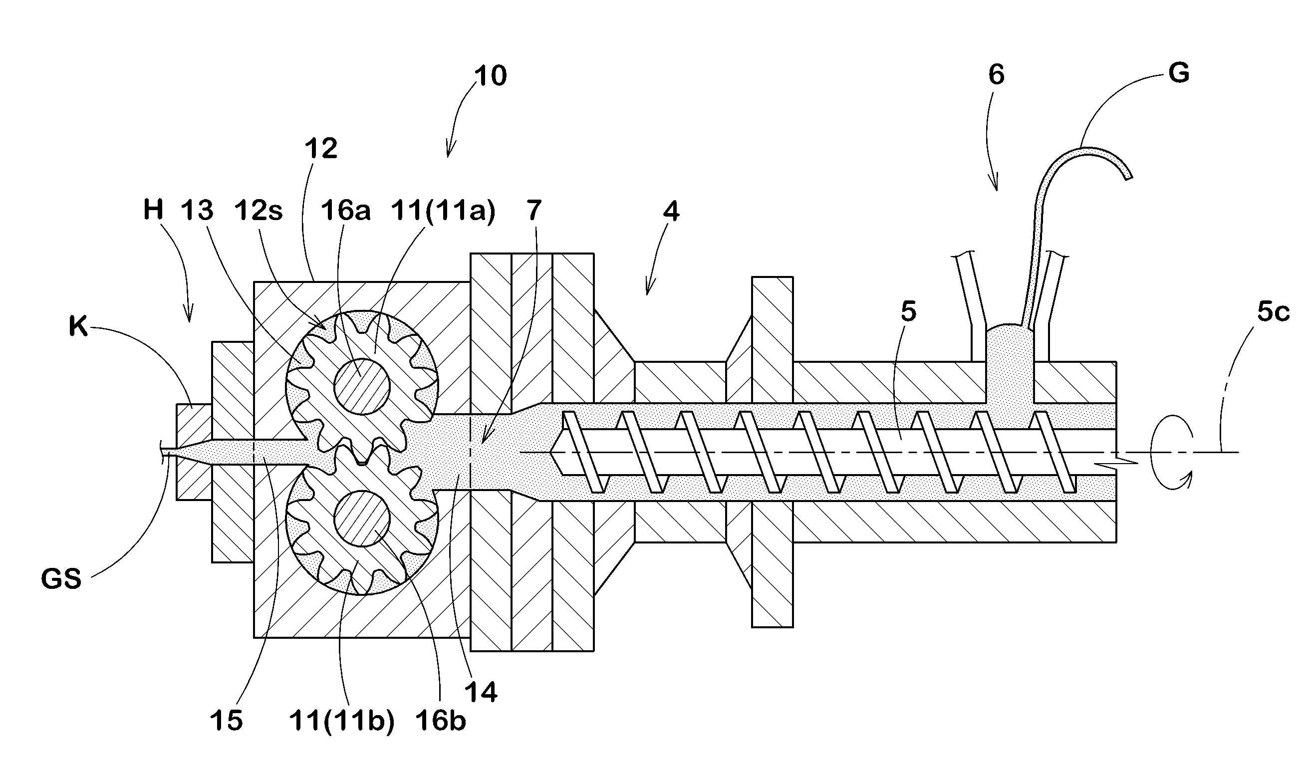
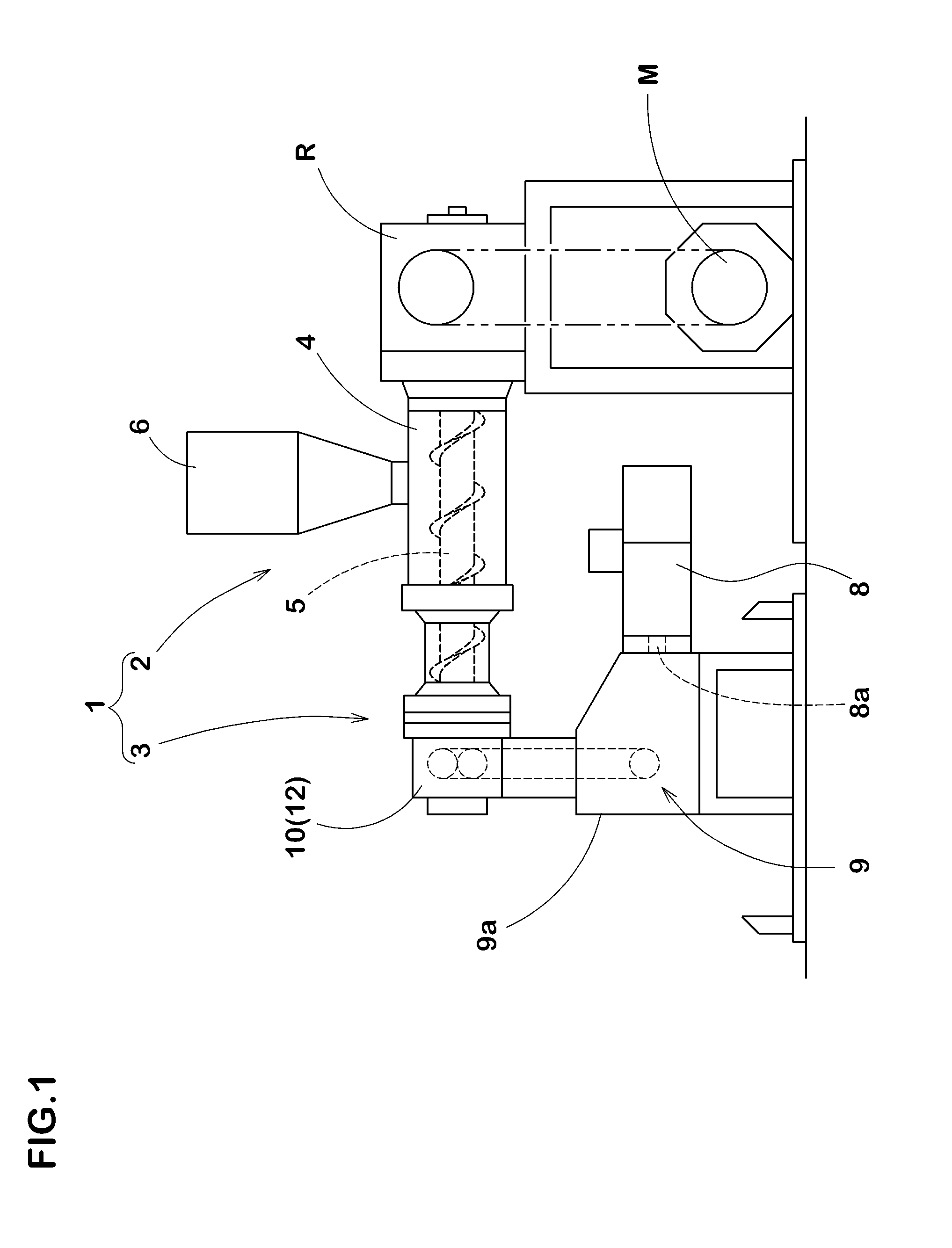
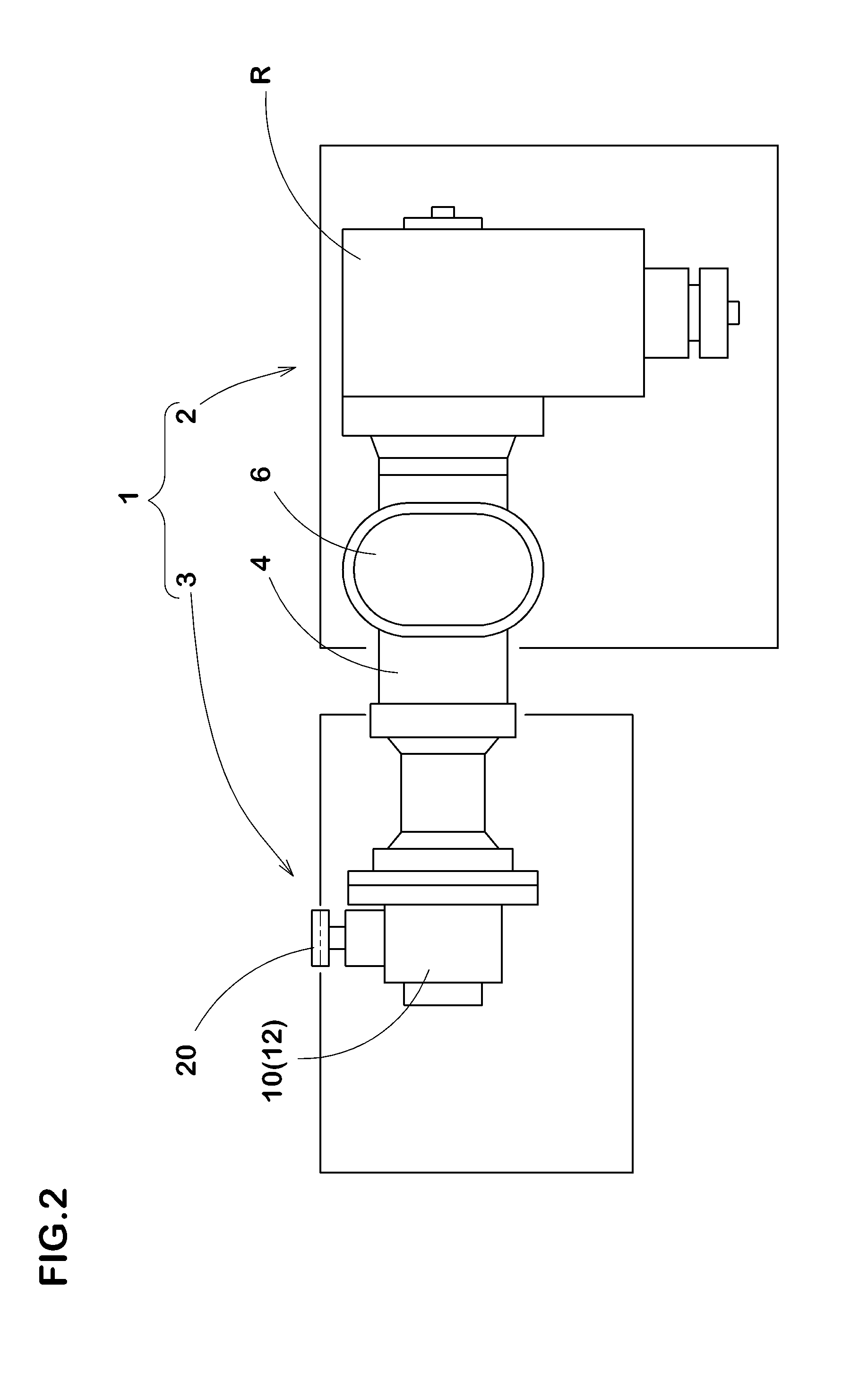
[0021]An embodiment of the present invention will be explained below reference to the accompanying drawings. As shown in FIGS. 1 to 3, a rubber extrusion device 1 in accordance with the present embodiment may knead unvulcanized rubber G (shown in FIG. 4) and extrude the same so as to form a continuously long ribbon-like rubber strip GS (shown in FIG. 4). On a certain downstream place of the rubber extrusion device 1, a rigid core (not shown) that has an outer surface similar to an inner cavity of a pneumatic tire to be manufactured can be provided. The rubber strip GS can be wound on the outer surface of the rigid core to form a green tire thereon.

[0022]The rubber extrusion device 1 in accordance with the present embodiment includes a rubber extruder 2 for extruding unvulcanized rubber, and a gear pump 3 linked to the rubber extruder 2.

[0023]The rubber extruder 2 includes a cylinder portion 4 including a screw shaft 5 therein, an electric motor M for driving the screw shaft 5, and a...


PUM

PropertyMeasurementUnit
torqueaaaaaaaaaa
shapeaaaaaaaaaa
opening shapeaaaaaaaaaa

Abstract

The present invention can save space. A rubber extrusion device (1) containing a rubber extruder (2) for kneading rubber and extruding same from a discharge port (7), and a gear pump (3) connected to the discharge port (7) of the rubber extruder (2). The rubber extruder (2) has a cylinder part (4), which houses a rubber extrusion screw (5), above the floor surface on which the rubber extruder (2) is placed. The gear pump (3) contains an electric motor (8), a decelerator (9) linked to the electric motor (8), and a gear pump main body (10) linked to the decelerator (9). A pair of gears (11) which meshes with one another is installed in the gear pump main body (10). The electric motor (8) and the decelerator (9) are disposed in a space below the gear pump main body (10) or the cylinder part (4). Moreover, the output shaft (9b) of the decelerator and one of the gears (11) are linked by means of a wrapping transmission means.

Description

TECHNICAL FIELD [0001]The present invention relates to a rubber extrusion device that may achieve a space saving.BACKGROUND ART [0002]Recently, as shown in FIG. 6(a), a method for producing a pneumatic tire where an unvulcanized ribbon-like rubber strip (a) is wound on an outer surface of a rigid core to form a green tire has been proposed. The rigid core has a shape similar an inner cavity of the pneumatic tire to be manufactured. In order to extrude the rubber strip (a), a rubber extrusion device (b) as shown in FIG. 6(b) has been proposed.[0003]The rubber extrusion device (b) includes a rubber extruder (c) and a gear pump (d), for instance. The rubber extruder (c) is configured to have a screw shaft for kneading unvulcanized rubber and ext riling the same. The gear pump (d) is configured to include a gear pump main body (h) that comprises an electric motor (f), a reduce (g) liked to the electric motor (f), and a pair of gears. The gear pump (d) receives extruded rubber from the ...

Claims


Application Information

Patent Timeline
Patent Type & Authority Applications(United States)
IPC IPC(8): B29C47/36B29C48/37B29C48/395
CPCB29C48/685B29C48/022B29C48/25B29C48/37B29C48/395B29D30/60B29B7/428B29B7/582B29B7/7495B29C48/387B29K2021/00B29L2031/001
Inventor ONIMATSU, HIROYUKI
Owner SUMITOMO RUBBER IND LTD
Why Eureka
Try Eureka