Systems and methods for fault detection using smart valves

a fault detection and smart valve technology, applied in the field of systems and methods for fault detection using smart valves, can solve the problems of no diagnostic nor fault mitigation capability, limited alarm capacity, and limited flexibility of alarm features currently available to detect faults, etc., and achieve the effect of reducing energy loss

Active Publication Date: 2015-08-20
BELIMO HOLDING AG
View PDF56 Cites 41 Cited by
  • Summary
  • Abstract
  • Description
  • Claims
  • Application Information

AI Technical Summary

Benefits of technology

[0010]In one aspect of the present invention, a fault detection system for detecting a lack of air flow in an air handler unit includes a coil located in an air stream of the air handler unit, the coil configured to operate as a conduit for process fluid in the system; air temperature sensors located in an air stream of the air handler unit, one temperature sensor located to determine an air temperature of air upstream of the coil and another temperature sensor located to determine an air temperature downstream of the coil; liquid temperature sensors located to determine a liquid temperature entering the coil and to determine a liquid temper

Problems solved by technology

However, this alarming capacity is limited.
However, alarm features currently available are very limi

Method used


Image

  • Systems and methods for fault detection using smart valves
  • Systems and methods for fault detection using smart valves
  • Systems and methods for fault detection using smart valves

Examples


Embodiment Construction

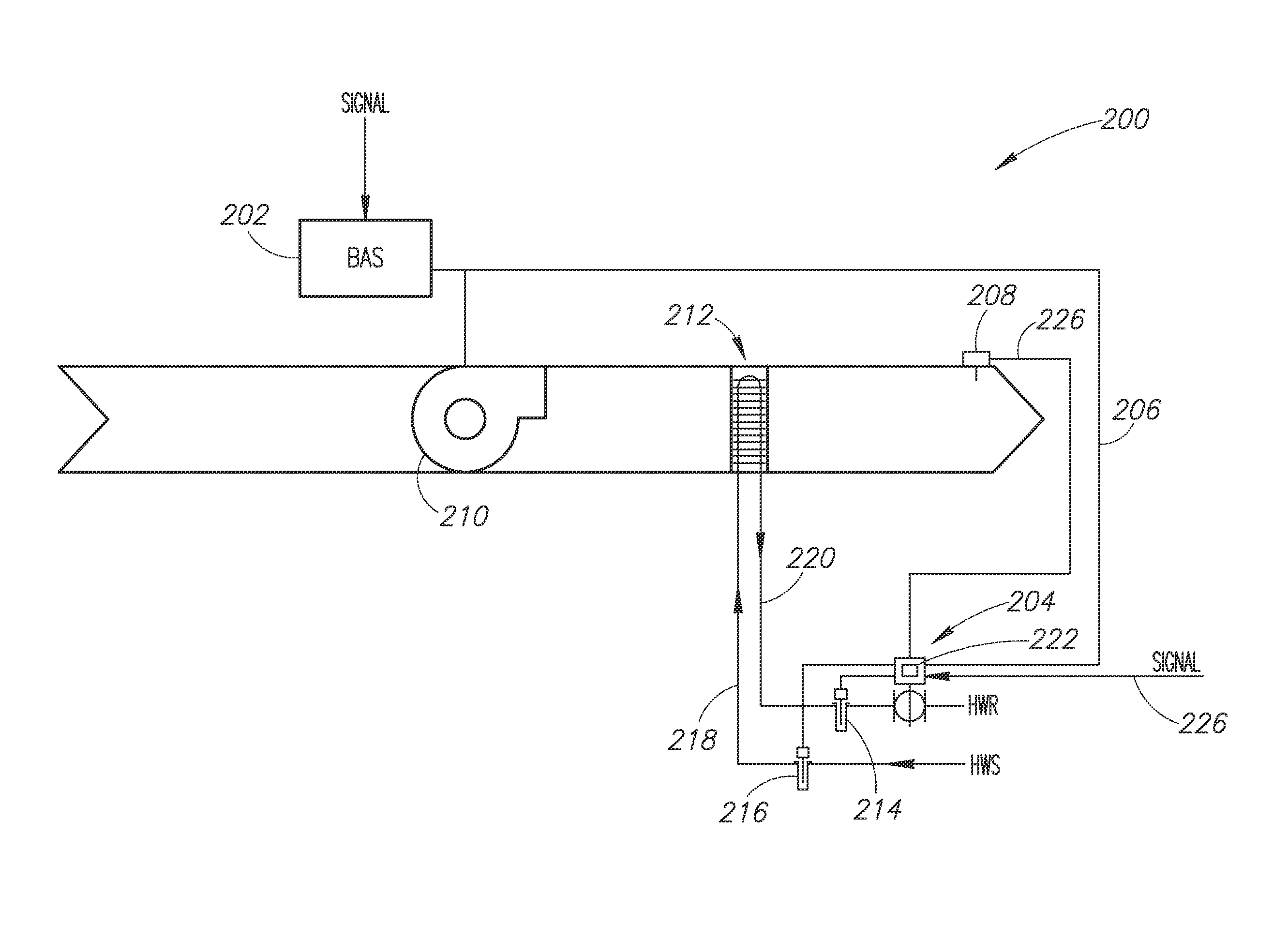
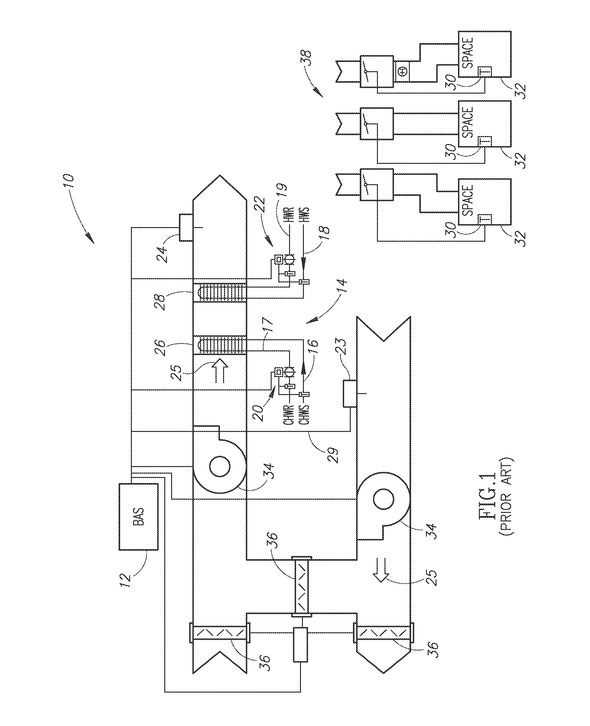
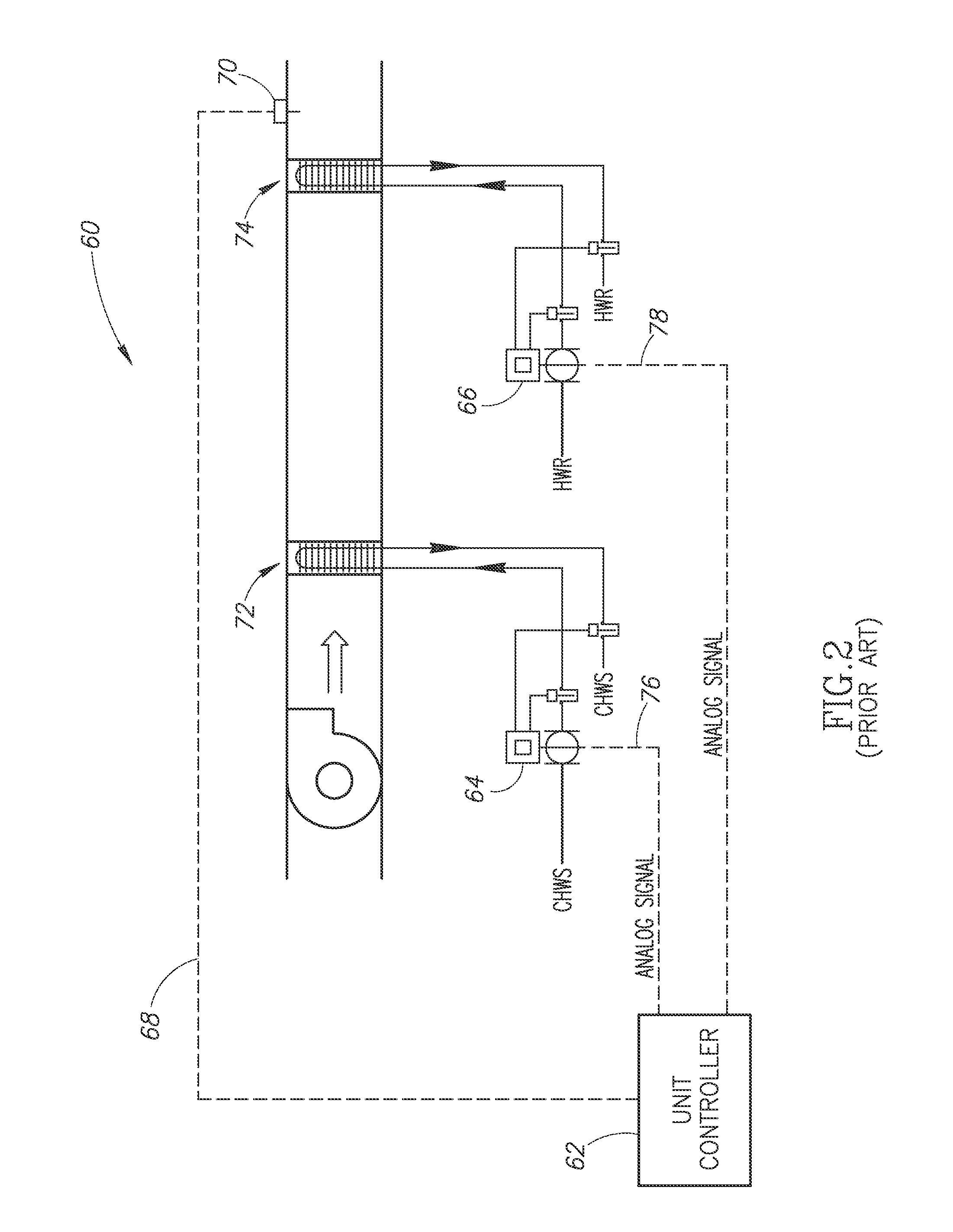
[0021]In the following description, certain specific details are set forth in order to provide a thorough understanding of various embodiments of the invention. However, one skilled in the art will understand that the invention may be practiced without these details. In other instances, well-known structures associated with HVAC systems; automation systems (e.g., building automation systems referred to as BASs); air handler units (AHUs) such as, but not limited to terminal units (also called fan coil units), packaged units or rooftop units, and various equipment used in AHUs such as, but not limited to, controllable valves, heating and cooling coils, various types of sensors; controllers and processors; communication networks; various computing and / or processing systems; various HVAC and / or AHU system operational parameters and set points; and methods of operating any of the above with respect to one or more buildings have not necessarily been shown or described in detail to avoid u...


PUM


Abstract

An air handler unit (AHU) in communication with a building automation system (BAS) or through direct programming of one or more smart valves within the AHU operates to meter an amount of water that flows through a coil in the AHU. In one embodiment, the BAS transmits a temperature setpoint signal to the smart valve and allows the smart valve to control its valve position without additional input from the BAS. In another embodiment, the AHU includes a master smart valve and a second valve. The BAS provides the temperature setpoint signal to the master smart valve, which in turn provides another temperature setpoint signal to the second valve. The second valve may take the form of a slave smart valve or a slave non-smart valve.

Description

PRIORITY[0001]This application is a continuation-in-part of and claims priority from U.S. patent application Ser. No. 14 / 108,725 filed on Dec. 17, 2013, and the subject matter of which is incorporated herein by reference in its entirety.FIELD OF THE INVENTION[0002]The present invention generally relates to systems and methods for selectively employing smart valves to detect, diagnose, and communicate complex hardware, programming and / or mechanical faults in an air handler unit (AHU) through an automation system or through direct communication of one or more smart valves within the AHU to one or more remote devices intended for the purpose.BACKGROUND[0003]Air handler units (AHUs) are commonly employed to condition and circulate air as part of a heating, ventilating, and air-conditioning (HVAC) system for buildings, and large buildings in particular. AHUs may provide heating, cooling, or both to change the supply air temperature, humidity level, or both depending on geographic locatio...

Claims


Application Information

Patent Timeline
IPC IPC(8): F24F11/00G01K13/02F24D19/10F24F3/08
CPCF24H3/08F24H9/2064F24F3/044F24F11/84F24F3/08F24D19/1006F24F11/30F24F2140/20F24F2110/10F24F11/83F24F11/38F24F11/63G01K13/02F24F11/56F24F11/32F24F11/62G01K13/024G01K13/026
Inventor DEMPSTER, IAN ROBERTERPELDING, BENJAMIN PAULHARTMAN, THOMAS BENNETTMACNEILL, CHELSEY ANN
Owner BELIMO HOLDING AG
Why Eureka
Try Eureka