

Automated profiling of the hardness of wood
- Summary
- Abstract
- Description
- Claims
- Application Information
AI Technical Summary
Benefits of technology
Problems solved by technology
Method used
Image

Examples
example 1
Probing Device for the Measurement of Hardness in a Wooden Structure
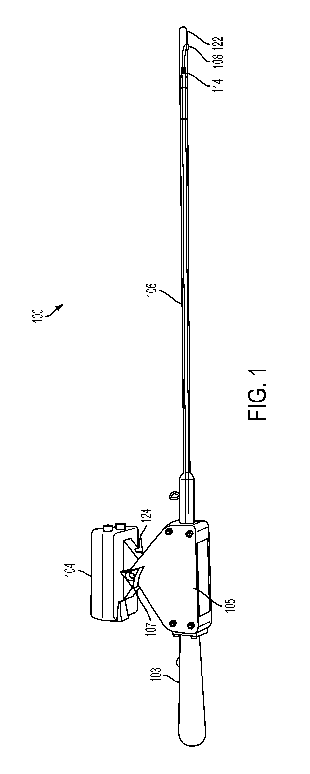
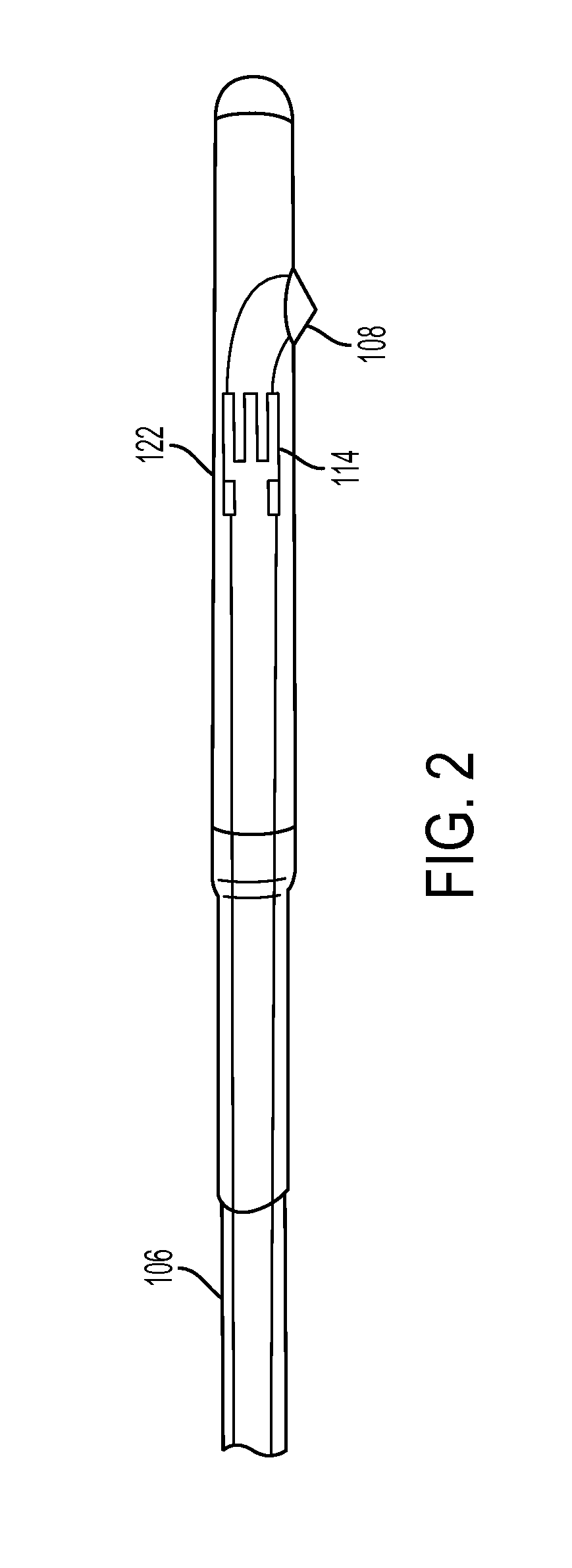
[0149]An exemplary probing device 100 of the present invention is depicted in FIGS. 1-6. The probing device 100 comprises a shaft 106, a horizontal handle 103, a distance sensor 104, a blade 108, and a mechanical sensor 114, as shown in FIG. 1. The shaft 106 comprises a probing tip 122 at the end of the shaft closest to the blade 108. The probing tip 122 surrounds the blade 108 such that the blade can retract into the probing tip 122 of the shaft 106. The mechanical sensor 114 is housed within the probing tip 122. A resistance mechanism is also housed within the shaft 106.
[0150]In this example, the probing tip 122 has a diameter slightly larger than the base of the shaft 106, as shown in FIG. 2. The end of the shaft 106 furthest from the blade is attached to an electronics unit 105, a horizontal handle 103, and a distance sensor 104, as shown in FIG. 3. The electronics unit 105 comprises a housing with electrical co...
example 2
Method of Profiling the Hardness of a Wooden Structure
[0153]In an exemplary method of the present invention, a probing device 100 is used to measure the hardness of a cross-section of a utility pole. The condition of the wood surrounding a first inspection hole is assessed by boring a hole along a first diameter of a utility pole. The exemplary probing device 100 depicted in FIG. 1 is then introduced into the first inspection hole and carefully inserted through the hole until the blade 108 of the device exits the first inspection hole at the opposite side of the utility pole. As the probing device 100 proceeds through the first inspection hole, the distance sensor 104 continuously measures the location of the blade 108 within the utility pole, and the mechanical sensor 114 continuously measures the strain on the blade 108 caused by contact with the surrounding wood. The location data and the strain data are transmitted to a computing device 116, as shown in FIGS. 13A-13B.
[0154]A sec...
example 3
Probing Device for the Measurement of Hardness in a Wooden Structure
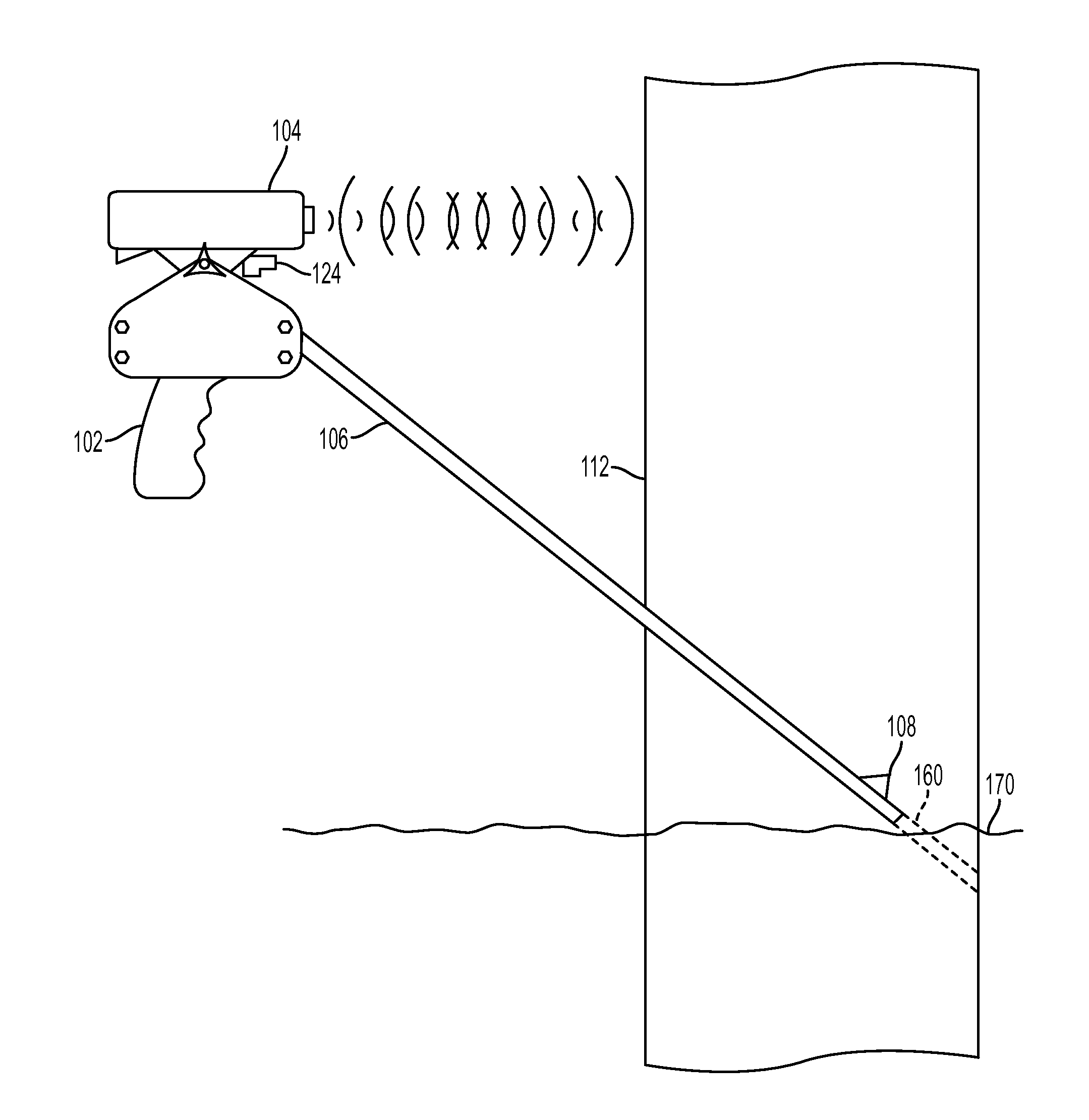
[0156]An exemplary probing device of the present invention is depicted in FIGS. 22 and 16-19. The probing device comprises a shaft 106, a raised handle 101, a distance sensor 104, a blade 108, and a dial 107, as shown in FIG. 22. The dial 107 allows a user to adjust the angle of the shaft to inspect an angled bored hole 160 in a wooden structure 112, for example, to inspect an area below the ground-line 170. The shaft 106 comprises a tube 106a, which is secured to the substantial remainder of the shaft by a pin 119, and the triangular metal blade 108 protrudes from an opening at one end of the tube 106a, as shown in FIG. 16. The shaft 106 further comprises a conical probing tip 122 secured by a pin 119 to the end of the tube 106a closest to the blade 106, such that the probing tip 122 is adjacent to the blade 108 and leads the blade 108 into a hole in the wooden structure.
[0157]The blade 108 is secured to a pivot ar...
PUM
 Abstract
Description
Claims
Application Information