Detachable machine control panel with display
- Summary
- Abstract
- Description
- Claims
- Application Information
AI Technical Summary
Benefits of technology
Problems solved by technology
Method used
Image
Examples
first embodiment
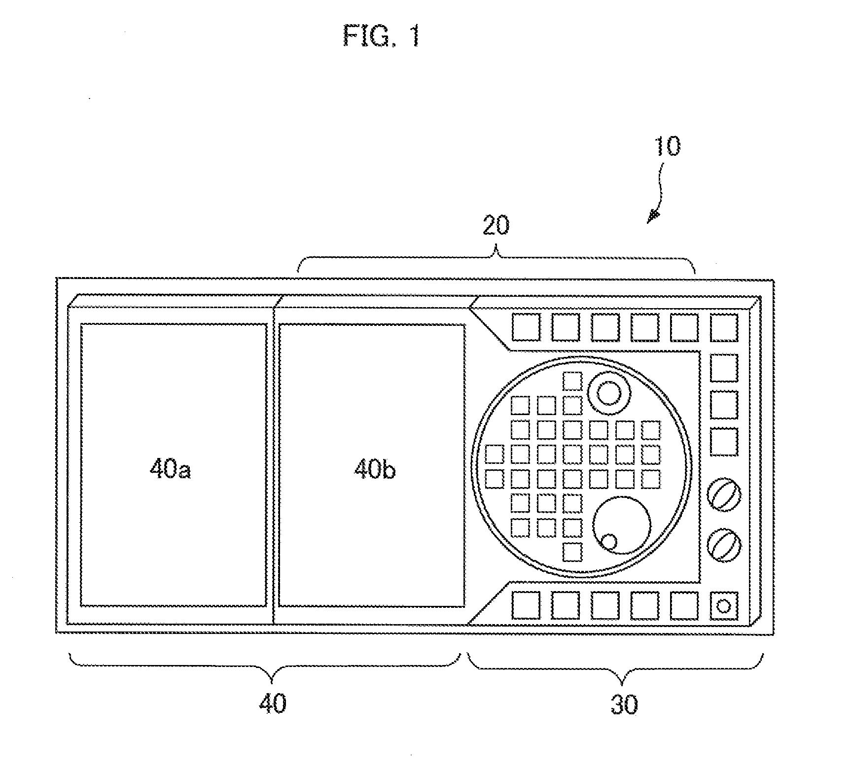
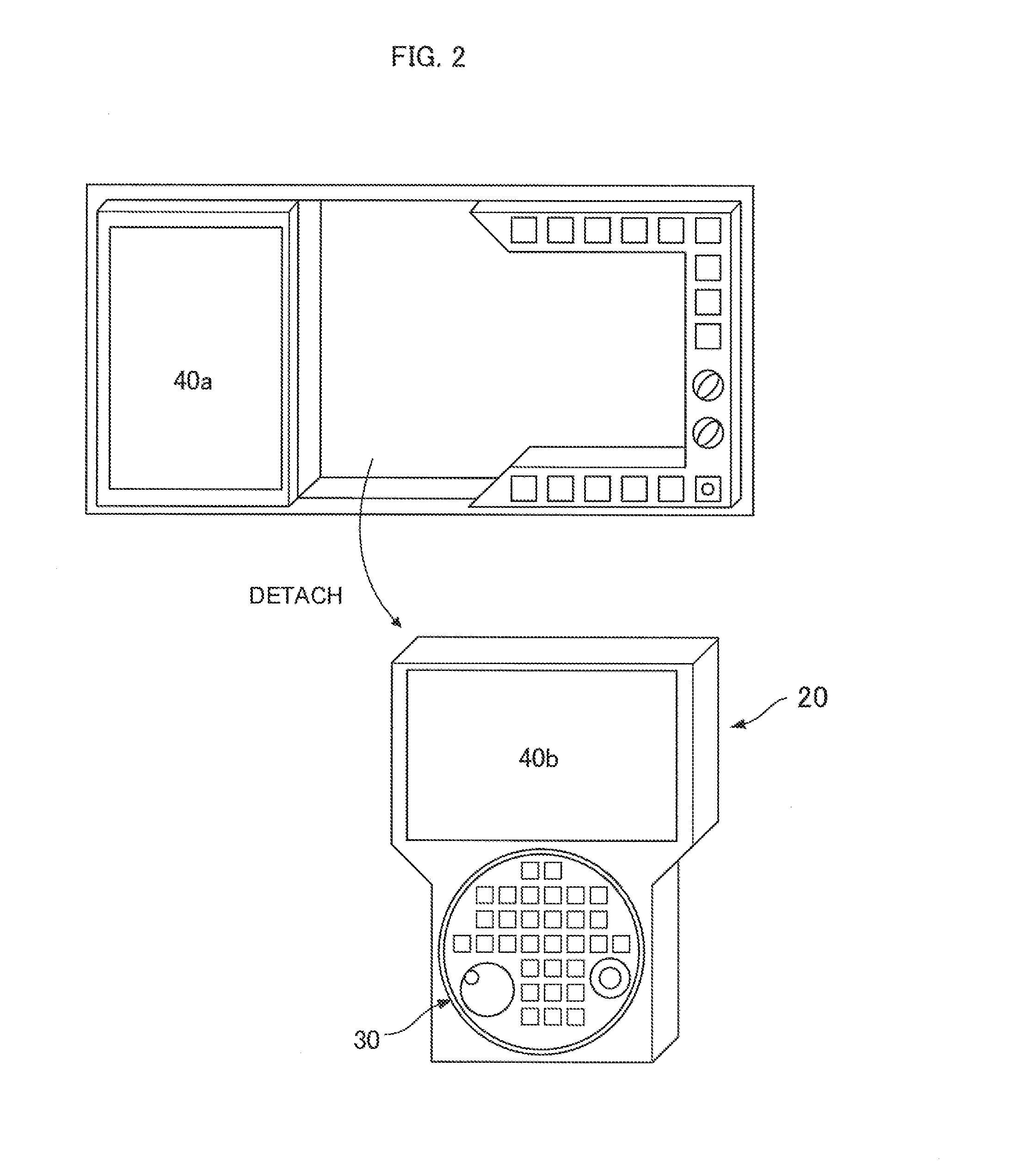
[0035]First, a machine control panel with a display according to the present invention is explained with reference to FIGS. 1 to 4.
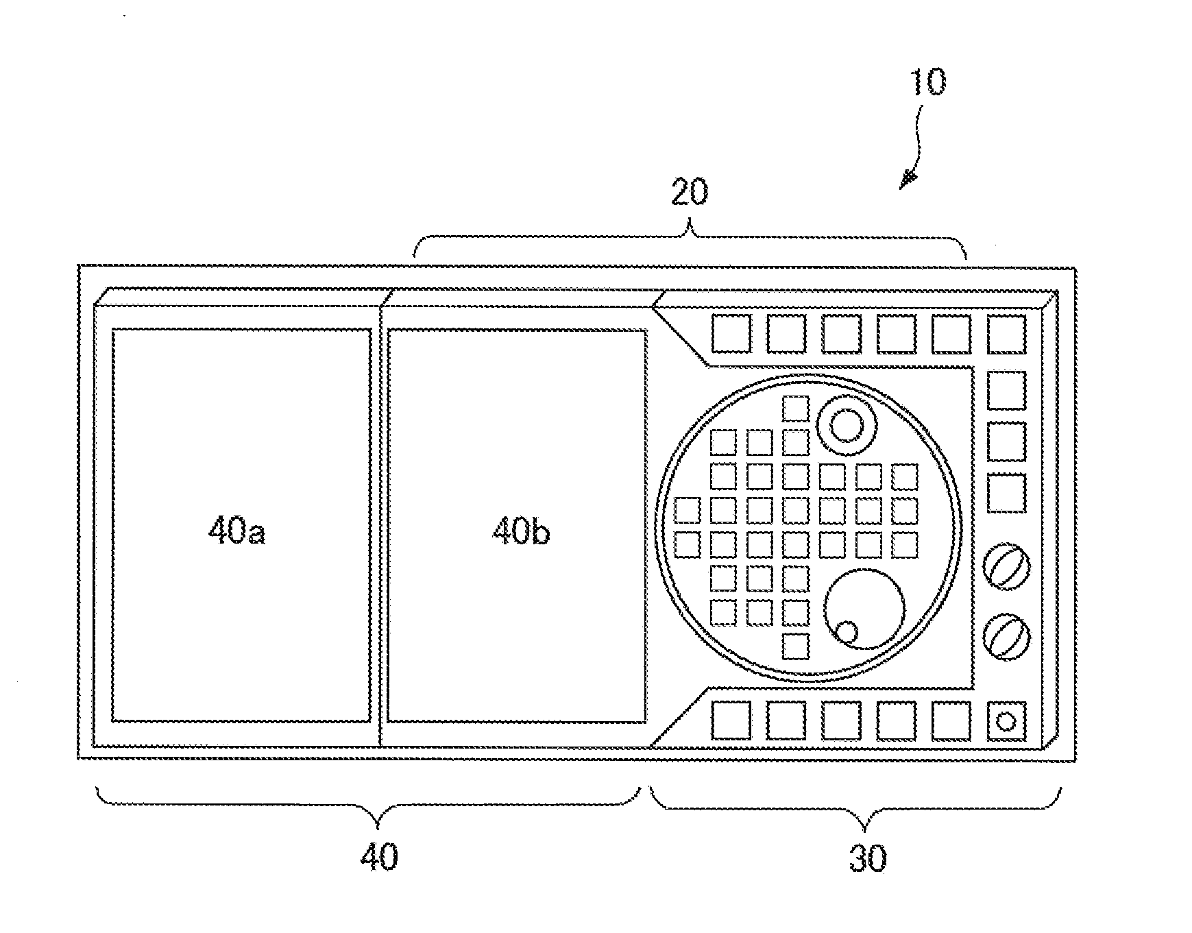
[0036]A machine control panel with a display 10 according to this embodiment includes, as shown in FIG. 1, an operation section 30 and a display section 40 disposed side by side with the operation section 30. The display section 40 is configured from two LCD panels having the same size, i.e., a first display section 40a and a second display section 40b.
[0037]The first display section 40a and the second display section 40b are disposed side by side on the left and right such that the long sides of the respective panels are in contact with each other as shown in FIG. 1. The first display section 40a is fixed to a main body (a control panel main body) of the machine control panel with the display 10. On the other hand, the second display section 40b configures a detachable section 20 in conjunction with a part of the operation section 30. As shown in FIG. ...
second embodiment
[0060]A machine control panel with a display according to the present invention is explained with reference to FIGS. 5 to 7.
[0061]The machine control panel with the display 10 according to this embodiment includes, as shown in FIG. 5, the operation section 30 and the display section 40 disposed side by side with the operation section 30. The display section 40 is configured from two LCD panels having the same size, i.e., the first display section 40a and the second display section 40b.
[0062]The first display section 40a and the second display section 40b are disposed side by side on the left and right such that the long sides of the respective panels are in contact with each other as shown in FIG. 5. The first display section 40a is fixed to a main body (a control panel main body) of the machine control panel with the display 10. On the other hand, the second display section 40b is configured to be independently detachable from the control panel main body as shown in FIG. 6A in a s...
third embodiment
[0072]A machine control panel with a display according to the present invention is explained with reference to FIG. 8.
[0073]FIG. 8 is a block diagram showing the machine control panel with the display 10 according to the third embodiment of the present invention and the numerical controller 62 of the machine tool 60 to which the machine control panel 10 is connected. In the figure, components same as the components in the block diagram in the first embodiment shown in FIG. 4 are denoted by the same names and explanation of the components is omitted.
[0074]In this embodiment, the graphic control section 108 in the main body side control section 70 in the first embodiment is omitted. Creation of image data performed by the graphic control section 108 in the first embodiment is performed by the CPU 64 of the numerical controller 62. The image data is written in the DRAM 66. The DMA controller 106 of the main body side control section 70 transfers the image data written in the DRAM 66 of...
PUM
 Abstract
Description
Claims
Application Information
 - R&D
- Intellectual Property
- Life Sciences
- Materials
- Tech Scout
- Unparalleled Data Quality
- Higher Quality Content
- 60% Fewer Hallucinations
Browse by: Latest US Patents, China's latest patents, Technical Efficacy Thesaurus, Application Domain, Technology Topic, Popular Technical Reports.
© 2025 PatSnap. All rights reserved.Legal|Privacy policy|Modern Slavery Act Transparency Statement|Sitemap|About US| Contact US: help@patsnap.com


