Fixing battery cells in place by compressed cell fixture

Active Publication Date: 2015-08-20
LISA DRAXLMAIER GMBH
View PDF16 Cites 9 Cited by
  • Summary
  • Abstract
  • Description
  • Claims
  • Application Information

AI Technical Summary

Benefits of technology

[0009]To fix the cells in place permanently, the cell fixture is then compressed by means of the two cell carriers by pressing the cell carriers together. If the direction of compression is the Z-direction, which, in the case of elongated cells, is their main direction of extension, the material of the cell fixture expands along spatial directions X and Y, which are perpendicular to the Z direction. Therefore, the material of the cell fixture may enclose every single cell evenly and firmly, regardless of any tolerances. The cells are fixed in place with simple means. Individual clamping, adapting, etc., of the cells is not necessary. As a result, vibrations and rattling noises when the battery is in use, such as with motor vehicle applications, are reduced. This increases a service life of the cell block and therefore the battery. In addition, the fixture shown here can be easily adapted to varying cell geometries and cell arrangements. Tolerances are compensated automatically

Problems solved by technology

For example, if sheet metal strips are soldered to the cells for contacting, the strips may experience fatigue due to vibration, and eventually break.
This problem is intensified in that the dimensions of the cells are subject to tolerances, which complicates fixing all cells dependably in place wit

Method used


Image

  • Fixing battery cells in place by compressed cell fixture
  • Fixing battery cells in place by compressed cell fixture

Examples


Embodiment Construction

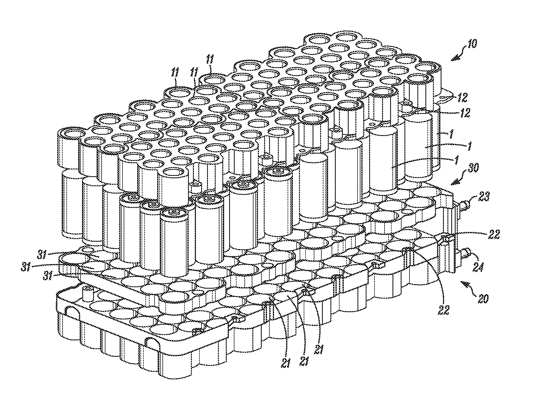
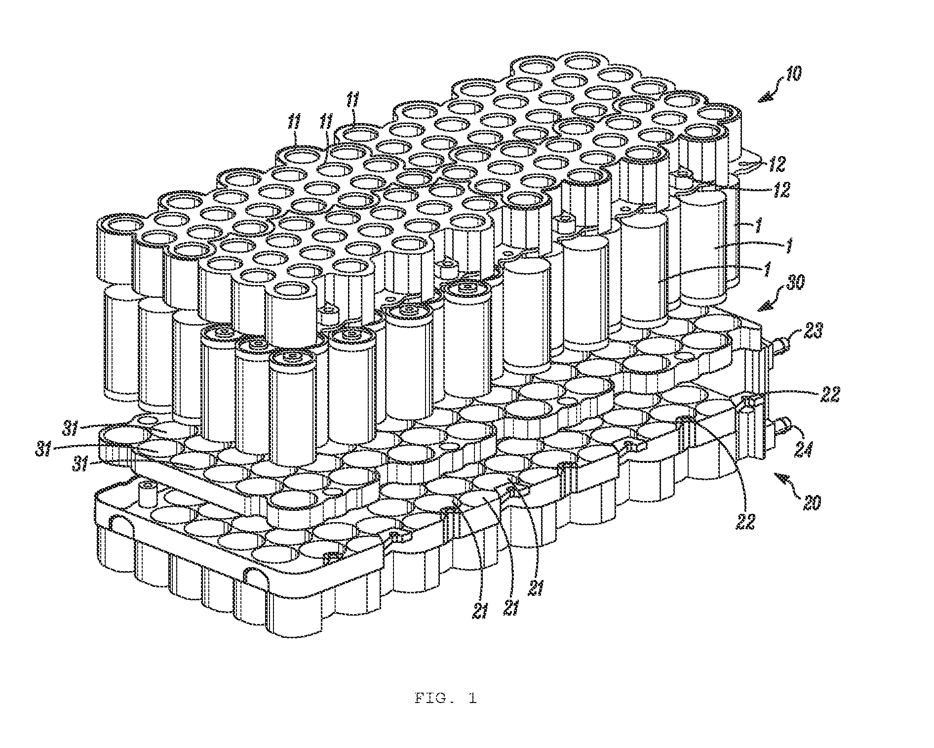
[0017]FIG. 1 is a perspective view of a cell block consistent with embodiments of the disclosure, in a drawn out manner to show individual components of the cell block.

[0018]Here, reference symbol 10 refers to an upper cell carrier, which may also be referred to as a first cell carrier, Reference symbol 20 refers to a lower cell carrier, which may also be referred to as a second cell carrier. Reference symbol 30 refers to a cell fixture.

[0019]The upper cell carrier 10, the lower cell carrier 20, and the cell fixture 30 each have openings 11, 21, and 31, respectively, through which and / or into which cells 1 are inserted. Whereas the cells 1 can be inserted through the openings 31, the openings 11 and 21 of the two cell carriers 10 and 20 are closed at one side or provided with a reduced radius so that the cells 1 are held by the cell carriers 10 and 20 and would not slide through the openings 11 and 21.

[0020]In some embodiments, the two cell carriers 10 and 20 are made of a synthetic...


PUM


Abstract

A method for fixing battery cells includes positioning each battery cell in a respective opening of a cell fixture; inserting a first side of each battery cell into a respective opening of a first cell carrier; inserting a second side, opposite to the first side, of each battery cell into a respective opening of a second cell carrier, such that the cell fixture is positioned between the first and second cell carriers; and pressing the first and second cell carriers together to compress the cell fixture.

Description

CROSS-REFERENCE TO RELATED APPLICATION[0001]This application is based upon and claims the benefit of prior German Application No. 10 2014 002 165.3, filed on Feb. 19, 2014, the entire contents of which are incorporated herein by reference.TECHNICAL HELD[0002]The disclosure relates to a method for fixing battery cells in place to create a cell block, as well as a cell block with a plurality of battery cells,BACKGROUND OF THE INVENTION[0003]High-voltage batteries have been used in motor vehicle applications, in particular in motor vehicles with hybrid drive or an all-electrical drive. Usually, such batteries have multiple battery cells, for example lithium ion cells, which are bundled as a cell block. In the present disclosure, unless otherwise specified, a “cell” refers to a battery cell.[0004]In a battery, individual cells, which may be developed as round cells, need to be fixed in place in such a fashion as to minimize vibrations, avoid rattling noises, and prolong a service life o...

Claims


Application Information

Patent Timeline
IPC IPC(8): H01M2/10H01M10/0525H01M50/213H01M50/227H01M50/262H01M50/264H01M50/293
CPCH01M2/1077H01M2220/20H01M10/0525H01M50/227H01M50/262H01M50/293H01M50/264H01M50/213Y10T29/4911Y02E60/10H01M50/107Y02P70/50
Inventor HOFER, GUIDOFALTERMEIER, PETER
Owner LISA DRAXLMAIER GMBH
Why Eureka
Try Eureka