Triggering circuit of the overvoltage protection

a triggering circuit and overvoltage protection technology, applied in spark gap circuits, emergency protective arrangements for limiting excess voltage/current, spark gap details, etc., can solve the problem of lack of protection function of overvoltage protection, the concept of overvoltage protection is not functional, and the current flowing through the triggering circuit oscillating character, etc. problem, to achieve the effect of safe design of the overvoltage protection triggering circuit and better triggering ability

Active Publication Date: 2015-08-20
SALTEK
View PDF9 Cites 6 Cited by
  • Summary
  • Abstract
  • Description
  • Claims
  • Application Information

AI Technical Summary

Benefits of technology

[0006]The overvoltage protection comprises a spark gap equipped with the first main electrode, the second main electrode, and one auxiliary electrode in order to make the breakdown between the first main electrode and the second main electrode easier, for which the design of the triggering circuit of the overvoltage protection is specified.
[0007]The advantages of such a design of the triggering circuit of overvoltage protection offer better triggering ability due to the functioning part of the design of the triggering circuit of the overvoltage protection, located on the primary side of the transformer.
[0008]To ensure the design of the overvoltage protection triggering circuit works safely, it is advantageous that the thermosensitive disconnector coupled with the thermal coupling to the second varistor, is either connected in series to the second varistor, or connected to the link of the junction connecting the second varistor to the resistor and the junction connecting the first input terminal to the first main electrode of the spark gap, or that the thermosensitive disconnector is connected between the primary winding of the transformer and the gas discharge tube.

Problems solved by technology

This design is simple, however, its correct functioning depends on the overvoltage pulse rise and so, in unfavorable circumstances, that is, if the rise of the pulse is low, i.e. the ratio of the voltage derivation to the time derivation is low, the auxiliary electrode of the spark gap will not activate and the discharge between the first main electrode and the second main electrode of the spark gap will not spark, which is the reason why the concept of overvoltage protection is not functional.
The disadvantage of these designs is the oscillation character of the current flowing through the triggering circuit of the overvoltage protection.
With the oscillation current flowing through the secondary winding of the transformer going through zero, the discharge can extinguish between one of the first main electrode or the second main electrode and the auxiliary electrode of the spark gap; whereas in such case the discharge between the first main electrode and the second main electrode of the spark gap will not be activated, which results in the absence of the protection function of the overvoltage protection.
This design of the triggering circuit of overvoltage protection eliminates in some respect the disadvantages of the previous designs, however, the oscillation character of the current flowing through the triggering circuit of the overvoltage protection still remains, and consequently the problem with possible discharge extinguishing between the first main electrode and the second main electrode of the spark gap, which results in the absence of the protective function of the overvoltage protection.

Method used


Image

  • Triggering circuit of the overvoltage protection
  • Triggering circuit of the overvoltage protection
  • Triggering circuit of the overvoltage protection

Examples


Embodiment Construction

OF THE TECHNICAL INVENTION′S IMPLEMENTATION

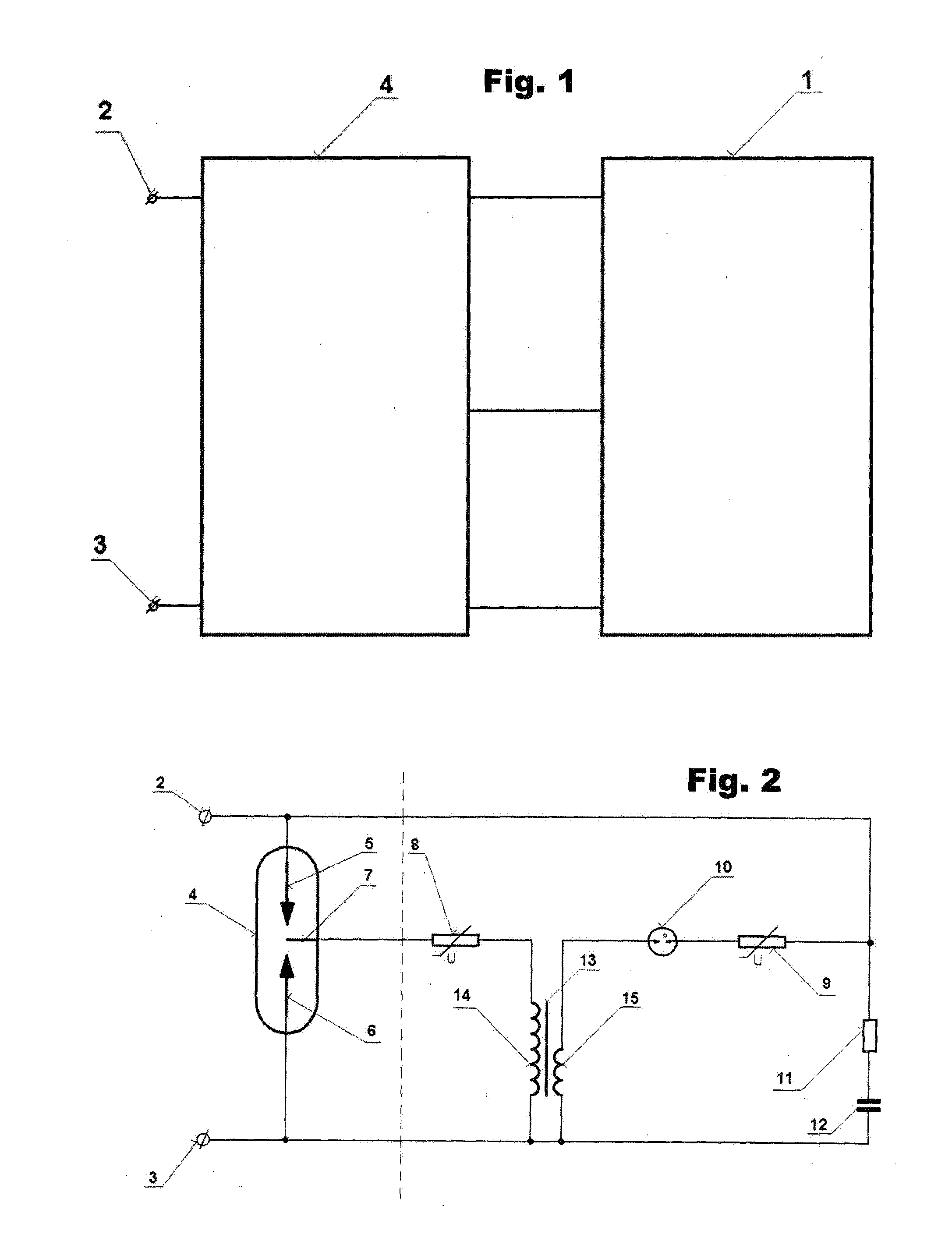
[0017]The overvoltage protection subject to FIG. 1 comprises a spark gap 4 of the overvoltage protection provided with the first input terminal 2 and the second input terminal 3, connected in three poles to a triggering circuit 1 of the overvoltage protection.

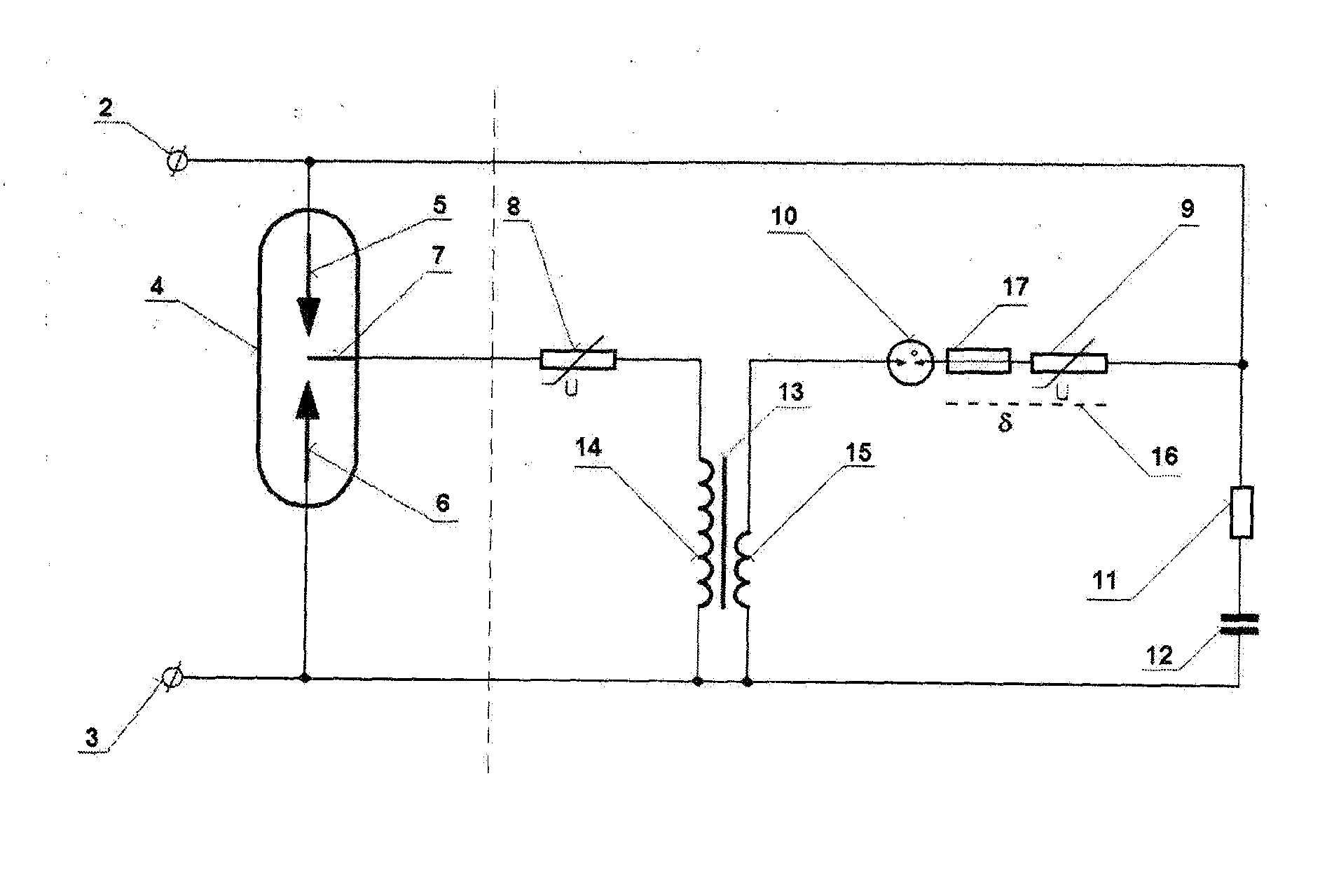
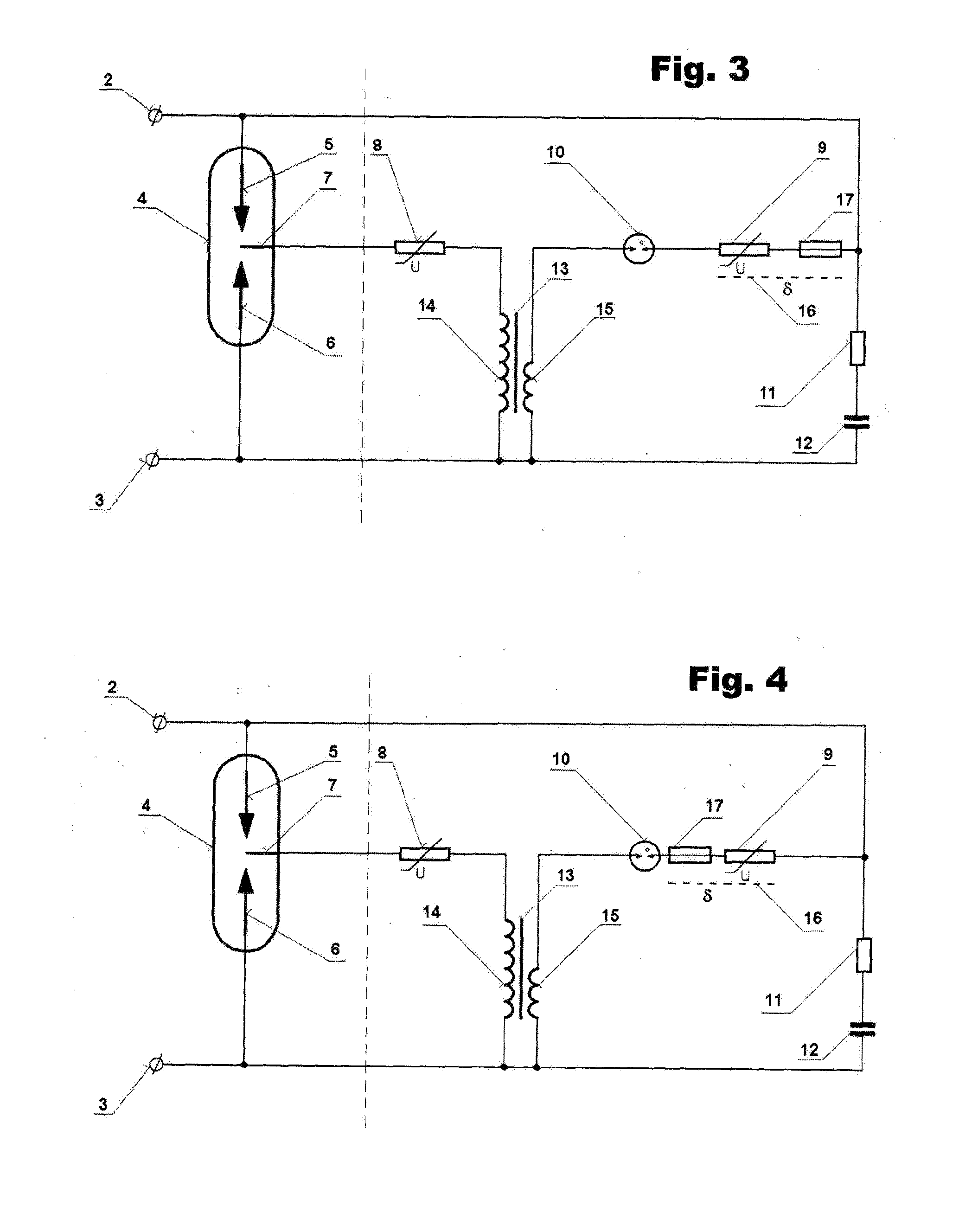
[0018]The basic design of the triggering circuit 1 of the overvoltage protection according to FIG. 2 comprises an auxiliary electrode 7 of the spark gap 4 which is connected in series to the first varistor 8 and one end of the secondary winding 14 of the transformer 13, the other end of which is connected to the second main electrode 6 of the spark gap 4 and to the second input terminal 3, whereas one end of the primary winding 15 of the transformer 13 is connected in series to a gas discharge tube 10, the second varistor 9, resistor 11 and capacitor 12, connected to the other end of the primary winding 15 of the transformer 13, connected to the second input terminal 3, whereas the jun...


PUM


Abstract

The design of the triggering circuit 1 of the overvoltage protection, connected via three poles 4 to the spark gap of the overvoltage protection, provided with the first input terminal 2 and the second main terminal 3, whose principle consists that an auxiliary electrode 7 of the spark gap 4 is connected in series to the first varistor 8 and one end of the secondary winding 14 of the transformer 13, the other end of which is connected to the second main electrode 6 of the spark gap 4 and the second input terminal 3, whereas one end of the primary winding 15 of the transformer 13 is connected in series to the gas discharge tube 10, the second varistor 9, resistor 11 and capacitor 12, connected to the other end of the primary winding 15 of the transformer 13, connected to the second input terminal 3, whereas the junction connecting the second varistor 9 to the resistor 11 is interconnected with the junction, connecting the first input terminal 2 to the first main electrode 5 of the spark gap 4.
The advantage of such a design of the triggering circuit 1 of overvoltage protection resides in the thermosensitive disconnector 17 coupled with the thermal coupling 16 to the second varistor 9, is either connected in series to the second varistor 9, or connected to the link of the junction connecting the second varistor 9 to the resistor 11 and the junction connecting the first input terminal 2 to the first main electrode 5 of the spark gap 4, or that the thermosensitive disconnector 17 is connected between the primary winding 15 of the transformer 13 and the gas discharge tube 10.

Description

TECHNOLOGICAL BACKGROUND[0001]This invention relates to the design of the triggering circuit of the overvoltage protection, representing electrical protection circuits designed to reduce overvoltage in a protected distribution system. The overvoltage protection comprises the spark gap of the overvoltage protection provided with the first input terminal, the second input terminal, interconnected in three poles with the triggering circuit of the overvoltage protection.CURRENT STATE OF TECHNOLOGY[0002]The known technical solutions of triggering circuit designs of overvoltage protection devices deal with the excitation of the transformer primary winding directly by is activating a gas discharge tube with an overvoltage impulse. This design is simple, however, its correct functioning depends on the overvoltage pulse rise and so, in unfavorable circumstances, that is, if the rise of the pulse is low, i.e. the ratio of the voltage derivation to the time derivation is low, the auxiliary ele...

Claims


Application Information

Patent Timeline
Patent Type & Authority Applications(United States)
IPC IPC(8): H01T15/00H01T1/00H01T2/02
CPCH02H1/04H02H9/005H02H9/042H02H9/06H01T1/00H01T2/02H01T15/00
Inventor SUCHY, JAROMIR
Owner SALTEK
Why Eureka
Try Eureka