Measurement device
a measurement device and measurement technology, applied in measurement devices, instruments, electrical testing, etc., can solve the problems of reducing the accuracy of measuring potentials of devices under test, unable to observe accurate change in voltage data, and inevitably generated leakage current, so as to achieve reduce leakage current. , the effect of long-term accurate measurement of voltag
- Summary
- Abstract
- Description
- Claims
- Application Information
AI Technical Summary
Benefits of technology
Problems solved by technology
Method used
Image
Examples
embodiment 1
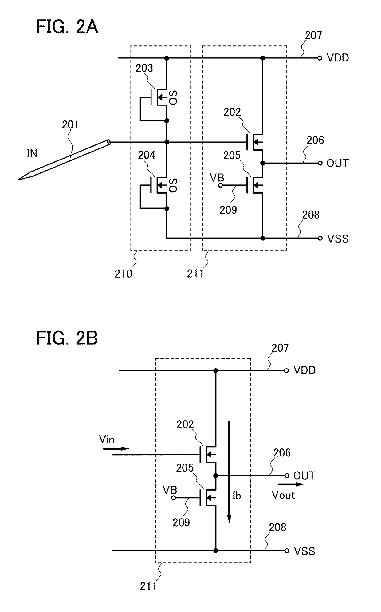
[0037]In this embodiment, one mode of a measurement device will be described with reference to FIGS. 2A and 2B.
[0038]FIG. 2A shows a circuit configuration of an input end of a measurement device, or more specifically, an active probe. In this embodiment, the active probe includes a probe needle 201, a protection circuit portion 210, and a detecting portion 211. The detecting portion 211 in this embodiment includes a power supply line 207 for applying a high-potential-side potential (VDD), a power supply line 208 for applying a low-potential-side potential (VSS: ground potential), and an output terminal 206. Thus, the detecting portion 211 is a circuit having three output terminals.
[0039]By physical contact with a device under test, the probe needle 201 serves as an interface for inputting, to the measurement device, voltage of a portion where the probe needle contacts the device under test (hereinafter the portion is referred to as contact portion). Therefore, the probe needle 201 i...
embodiment 2
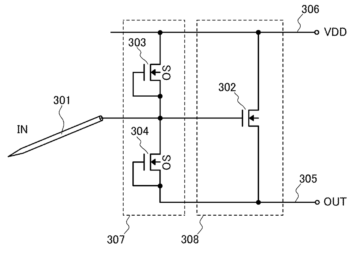
[0059]In Embodiment 1, the measurement device including the detecting portion having three output terminals is described. In this embodiment, a measurement device including a detecting portion having two output terminals will be described with reference to FIG. 3.
[0060]FIG. 3 shows a circuit configuration of an input end of a measurement device, or more specifically, an active probe. In this embodiment, the active probe includes a probe needle 301, a protection circuit portion 307, and a detecting portion 308. The detecting portion 308 in this embodiment includes a power supply line 306 for applying a high-potential-side potential (VDD) and an output terminal 305. Thus, the detecting portion 308 is a circuit having two output terminals.
[0061]The probe needle 301 is electrically connected to the detecting portion 308 via the protection circuit portion 307.
[0062]The detecting portion 308 includes a MOSFET 302. In this embodiment, the MOSFET 302 is an n-channel transistor. The MOSFET 3...
embodiment 3
[0068]In Embodiment 1, the case of using n-channel MOSFETs in the detection portion having three output terminals in the measurement device is described. In this embodiment, the case of using p-channel MOSFETs will be described with reference to FIG. 4.
[0069]FIG. 4 shows a circuit configuration of an input end of a measurement device, or more specifically, an active probe. In this embodiment, the active probe includes a probe needle 401, a protection circuit portion 410, and a detecting portion 411. The detecting portion 411 in this embodiment includes a power supply line 407 for applying a high-potential-side potential (VDD), a power supply line 408 for applying a low-potential-side potential (VSS: ground potential), and an output terminal 406. Thus, the detecting portion 411 is a circuit having three output terminals.
[0070]The probe needle 401 is electrically connected to the detecting portion 411 via the protection circuit portion 410.
[0071]The detecting portion 411 includes two ...
PUM
 Abstract
Description
Claims
Application Information
 - R&D
- Intellectual Property
- Life Sciences
- Materials
- Tech Scout
- Unparalleled Data Quality
- Higher Quality Content
- 60% Fewer Hallucinations
Browse by: Latest US Patents, China's latest patents, Technical Efficacy Thesaurus, Application Domain, Technology Topic, Popular Technical Reports.
© 2025 PatSnap. All rights reserved.Legal|Privacy policy|Modern Slavery Act Transparency Statement|Sitemap|About US| Contact US: help@patsnap.com


