
Method for operation of a fuel cell system in a vehicle

a fuel cell and vehicle technology, applied in the direction of transportation fuel cell technology, electric hydrogen generators, transportation, etc., can solve the problems of reducing the service life of the fuel cell system, so as to achieve convenient and efficient transportation, maintain readiness for operation, and no corrosion

Active Publication Date: 2015-05-19
CELLCENTRIC GMBH & CO KG
View PDF27 Cites 4 Cited by
  • Summary
  • Abstract
  • Description
  • Claims
  • Application Information

AI Technical Summary

Benefits of technology

[0002]Stop / start systems in vehicles are known from the general prior art, and are used for saving energy and reducing noise emissions by switching off the drive unit during short phases, in which no power is required, for example at a junction, a red traffic light or when the vehicle is rolling, in order to thus save energy. Typically, besides the drive unit itself, auxiliary consumers such as for example, pumps, compressors and the like are also switched off or at least brought into a state of reduced power. It is thus possible to clearly reduce both the energy requirement and the emission of harmful substances and noise.
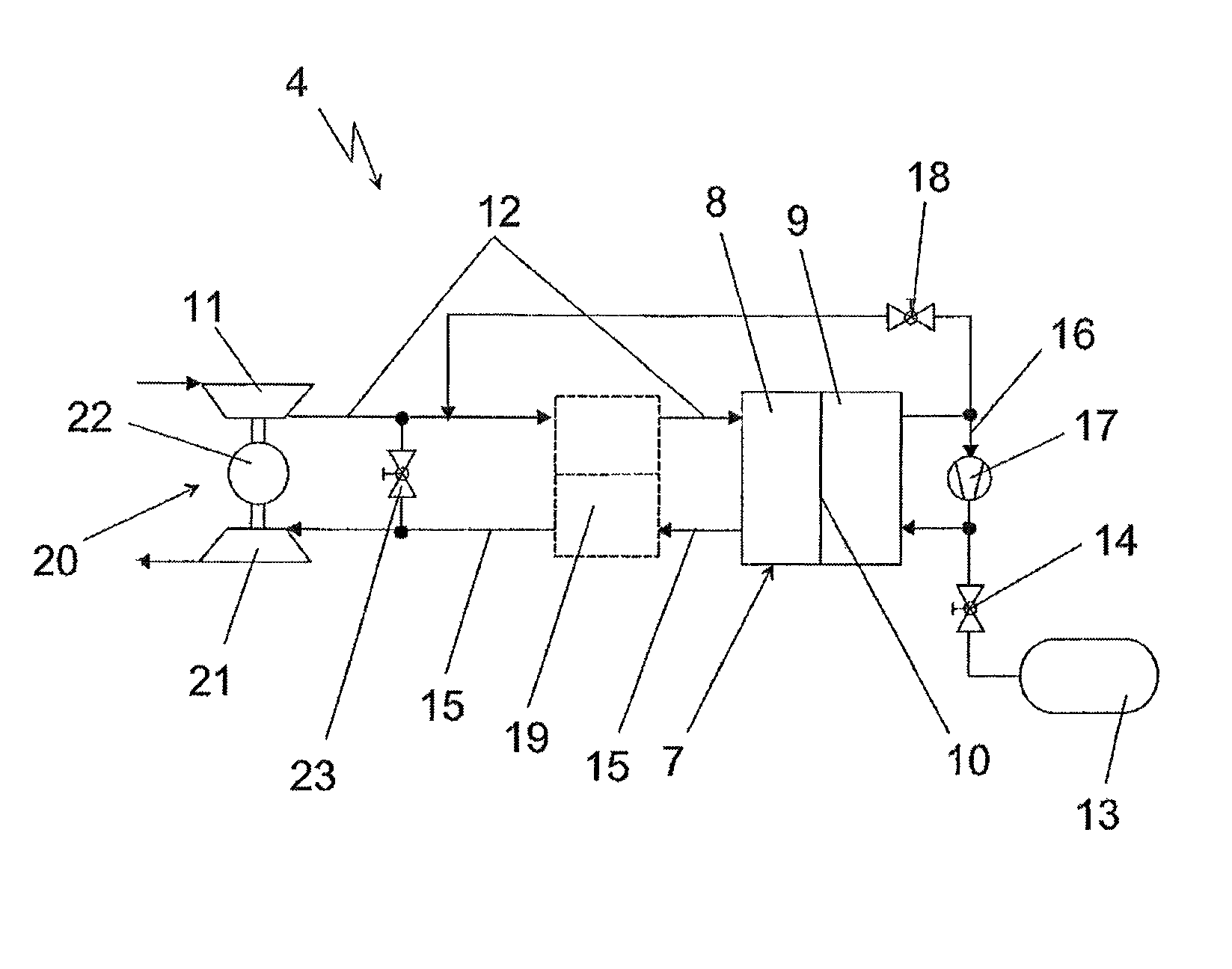
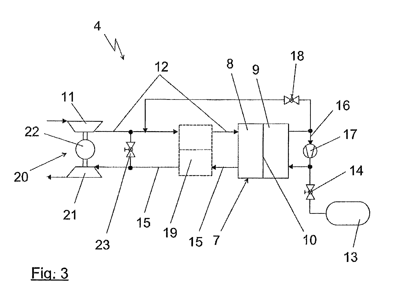
[0011]In a very favorable and advantageous further development of the inventive method it is now also provided that when switching to the stop mode between the air mass flow to the fuel cell after the air conveying device and an exhaust gas flow from the fuel cell system a flow connection is opened. Such a flow connection, which could also be described as a system bypass valve, thus creates a flow connection from a region after the air conveying device into the exhaust gas region. Without blocking off the cathode region of the fuel cell, which would necessitate very high-resource and expensive valve devices that are additionally prone to breakdown, very heavy and require a considerable construction space, it is thus possible with a single very simple valve to ensure that, for the possibly still conveyed air mass flow or the air mass flow built up through a build-up pressure for example during rolling down a hill of a vehicle, a path with a very low pressure loss is made available, via which a large part of the air mass flow can flow directly again away from the fuel cell system without previously passing the fuel cell. The quantity of oxygen conveyed into the fuel cell or its cathode chamber is thereby correspondingly reduced. It is nonetheless sufficient to prevent the abovementioned problems in relation to corrosion even without a refresh insofar as the air conveying device is formed as a flow compressor and continues to run at a low speed.

Problems solved by technology

However, the method described therein has the significant disadvantage that through the constant switching on and off comparatively rapid ageing of the fuel cell arises and for a restart both of the hydrogen supply and the air supply from a complete standstill a comparatively long time is required, in which upon restart of the vehicle the fuel cell cannot supply any drive power.
It can thereby arise by all means that a negative current flows into the fuel cell, the power necessary for this can be removed from the energy storage device and is typically very low.

Method used


Image

  • Method for operation of a fuel cell system in a vehicle
  • Method for operation of a fuel cell system in a vehicle
  • Method for operation of a fuel cell system in a vehicle

Examples


Embodiment Construction

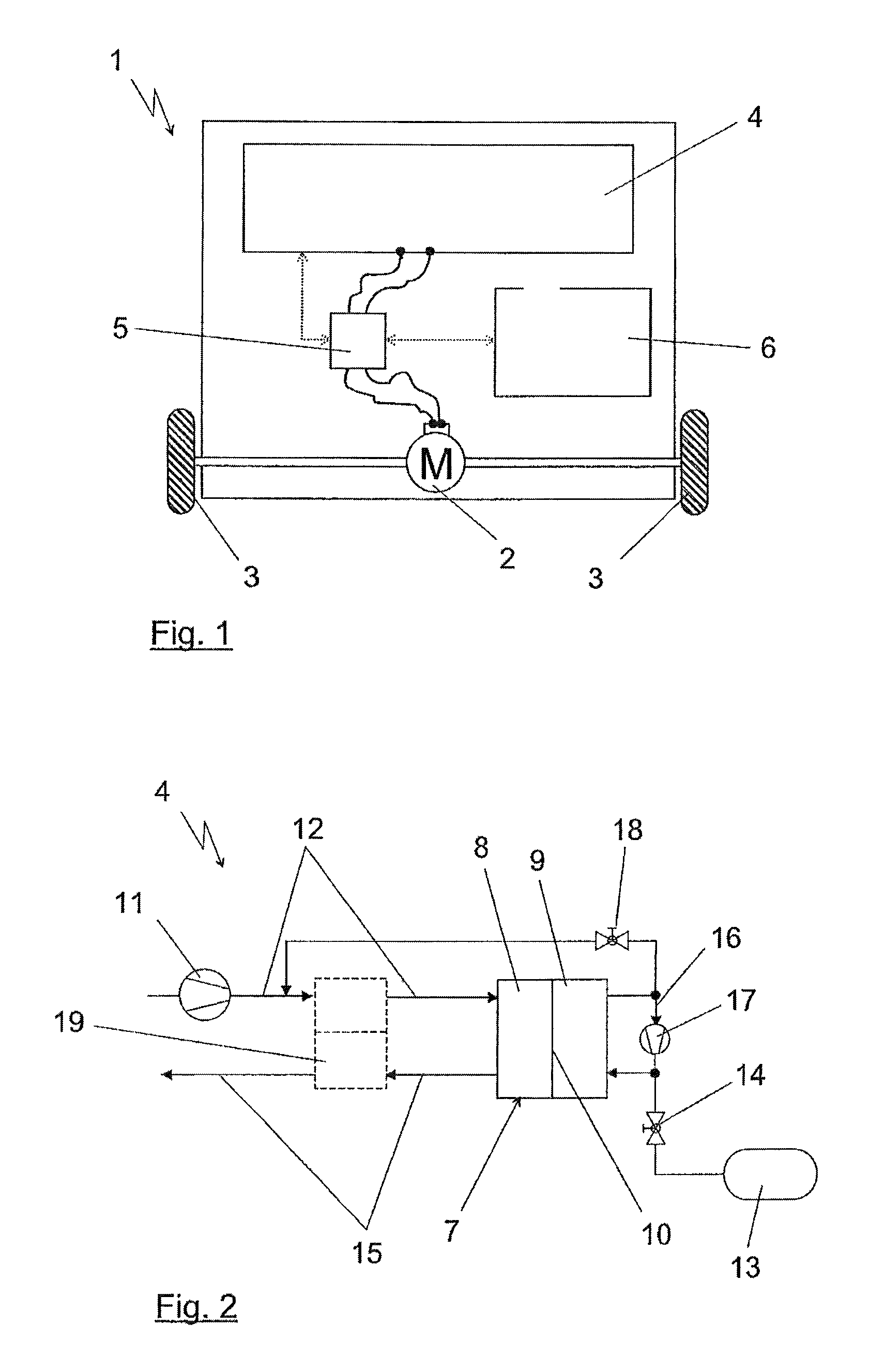
[0016]FIG. 1 shows a vehicle 1 in a greatly schematized representation, which can be moved via an electric drive motor 2 that drives two wheels 3. The vehicle 1 has a fuel cell system 4 providing the electric drive energy for the motor 2 and thus ultimately for driving the vehicle 1. This is shown in FIG. 1 via electric lines which connect the fuel cell system 4 and the drive motor 2 via an electronic unit 5 to each other. As indicated through the dotted arrows, the electronic unit 5 is also in communication with the fuel cell system 4 in order to be able to inquire, for example, about values of sensors in the fuel cell system 4 monitoring it with regard to pressure, temperature and the like. The electronic unit 5 is also in corresponding connection with a vehicle control unit 6 that is provided in the known way for controlling the vehicle. This vehicle control unit 6 is also in connection via sensors and actuators (not shown here) with the vehicle 1 and can evaluate for example acc...


PUM

PropertyMeasurementUnit
voltageaaaaaaaaaa
timeaaaaaaaaaa
hydrogen pressureaaaaaaaaaa

Abstract

A method of operating a fuel cell system in a vehicle that is switchable to a temporary stop mode and restarted from the stop mode. When, in certain driving situations, it is required to switch to the stop mode, it is then checked whether the operating conditions of the fuel cell system allow a switch to the stop mode. If the switch is allowed it takes place. When a restart of the fuel cell system is required on the basis of the vehicle the settings of the stop mode are cancelled again. The switch to the stop mode involves, with further existing electric contacting of the fuel cell, the air mass flow conveyed by the air conveying device being switched off or reduced to a predefined value and the pressure of the combustion gas supplied being reduced to a predefined value.

Description

BACKGROUND AND SUMMARY OF THE INVENTION[0001]The invention relates to a method for operating a fuel cell system in a vehicle, and in particular to a method of operating a fuel cell system in which the fuel cell system is switchable into and out of a temporary stop mode.[0002]Stop / start systems in vehicles are known from the general prior art, and are used for saving energy and reducing noise emissions by switching off the drive unit during short phases, in which no power is required, for example at a junction, a red traffic light or when the vehicle is rolling, in order to thus save energy. Typically, besides the drive unit itself, auxiliary consumers such as for example, pumps, compressors and the like are also switched off or at least brought into a state of reduced power. It is thus possible to clearly reduce both the energy requirement and the emission of harmful substances and noise.[0003]Start / stop systems are also known in vehicles equipped with a fuel cell system for generat...

Claims


Application Information

Patent Timeline
Patent Type & Authority Patents(United States)
IPC IPC(8): H01M8/04H01M8/10
CPCH01M8/04097H01M8/04111H01M8/04753H01M8/04776H01M8/0488H01M2008/1095H01M2250/20Y02T90/32Y02E60/50Y02T90/40
Inventor MUELLER, HELMUTSCHMALZRIEDT, SVENWEIGELE, KLAUS
Owner CELLCENTRIC GMBH & CO KG
Learn More