Core needle biopsy device

a biopsy device and core needle technology, applied in the field of biopsy devices, can solve the problems of limited capability and/or difficult use of devices, and achieve the effect of improving the accuracy and convenience of us

Active Publication Date: 2015-08-27
CR BARD INC
View PDF13 Cites 16 Cited by
  • Summary
  • Abstract
  • Description
  • Claims
  • Application Information

AI Technical Summary

Problems solved by technology

However, such devices typically have limi

Method used


Image

  • Core needle biopsy device
  • Core needle biopsy device
  • Core needle biopsy device

Examples


Embodiment Construction

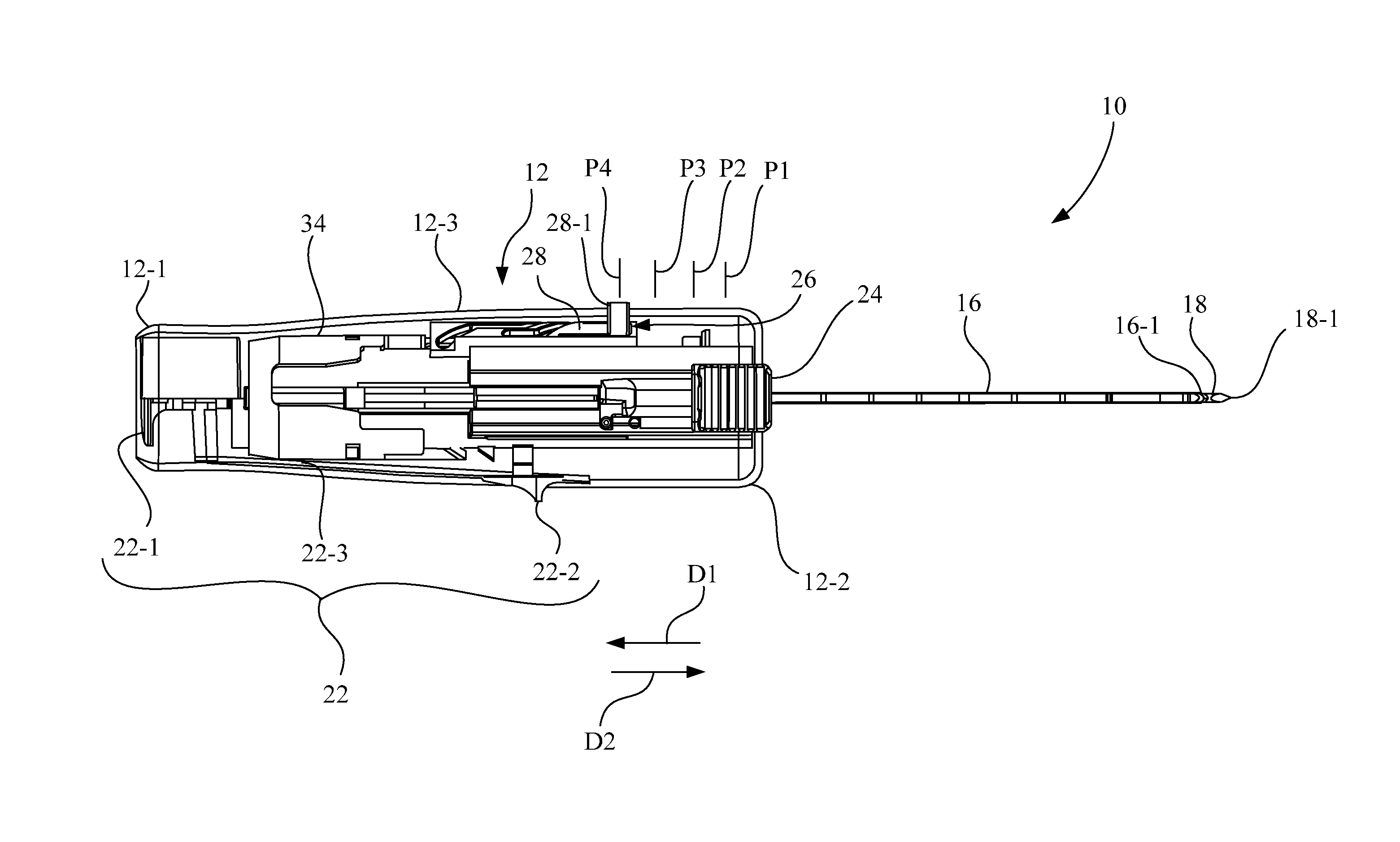
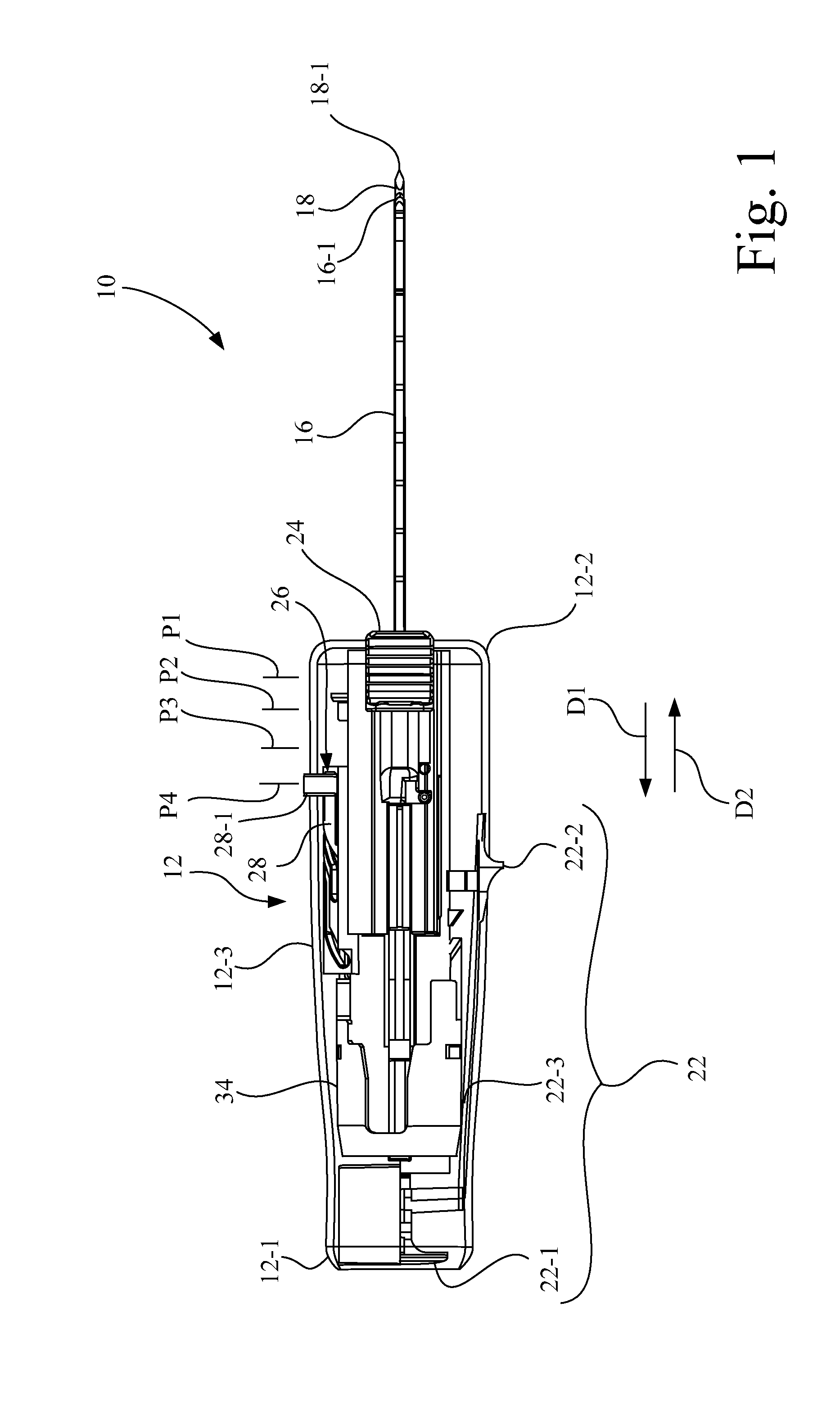
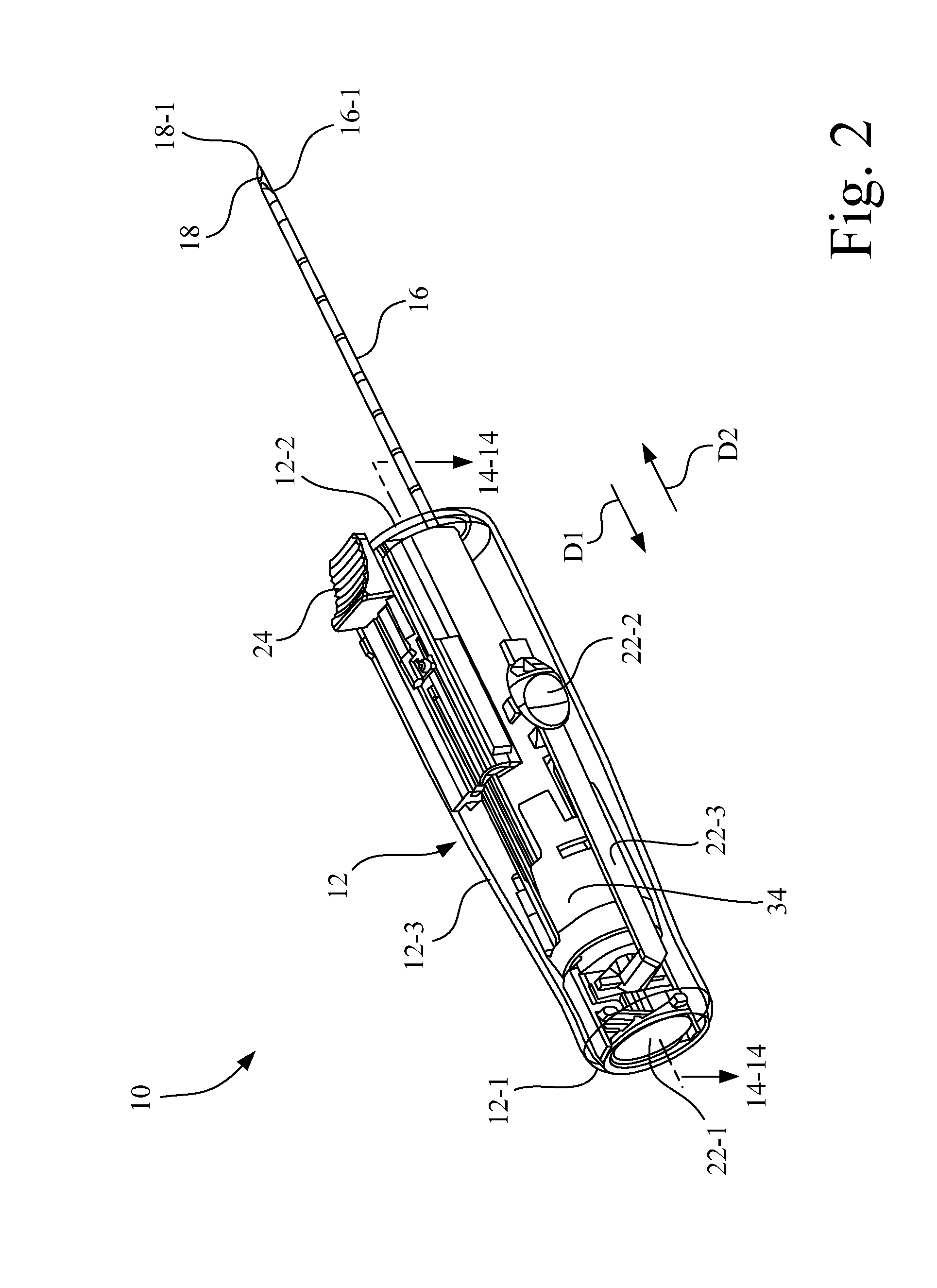
[0032]Referring now to the drawings, and more particularly to FIGS. 1-5, there is shown a core needle biopsy device 10 configured in accordance with an embodiment of the present invention. Core needle biopsy device 10 includes an outer housing 12 having a proximal end 12-1, a distal end 12-2, and a side wall 12-3. Side wall 12-3 defines an interior chamber 12-4 having a central axis 14. For ease of understanding the invention, FIGS. 1 and 2 show core needle biopsy device 10 with outer housing 12 depicted as being transparent, while FIG. 3 shows core needle biopsy device 10 with outer housing 12 removed.

[0033]Extending distally from distal end 12-2 of outer housing 12 is a cutting cannula 16 and an inner stylet 18. Inner stylet 18 is slidably received within the lumen of cutting cannula 16, with cutting cannula 16 and inner stylet 18 being coaxial with respect to an axis 20 (see FIG. 3). Axis 20 is parallel to, and radially offset from, central axis 14. Cutting cannula 16 is a hollow...


PUM


Abstract

A biopsy device includes a cutting cannula mechanism having a cutting cannula and an inner stylet mechanism having an inner stylet coaxial with the cutting cannula. A cocking mechanism is configured to cock the cutting cannula mechanism and the inner stylet mechanism by retracting each of the cutting cannula and the inner stylet in a proximal direction to a cocked position. A trigger device is configured to fire at least one of the inner stylet mechanism and the cutting cannula mechanism to advance a respective at least one of the inner stylet and the cutting cannula from the cocked position in a distal direction. A selector assembly includes a selector switch having an exterior tab accessible by a user. The selector assembly is configured to select between at least two user selectable operating modes and at least two user selectable firing distances.

Description

CROSS-REFERENCE TO RELATED APPLICATIONS[0001]This application claims priority to U.S. Provisional Patent Application Ser. No. 61 / 729,245 entitled “CORE NEEDLE BIOPSY DEVICE” filed Nov. 21, 2012, and U.S. Provisional Patent Application Ser. No. 61 / 774,293 entitled “CORE NEEDLE BIOPSY DEVICE” filed Mar. 7, 2013, each of which is incorporated herein by reference.BACKGROUND OF THE INVENTION[0002]1. Field of the Invention[0003]The present invention relates to biopsy devices, and, more particularly, to a handheld core needle biopsy device.[0004]2. Description of the Related Art[0005]Some practitioners that perform biopsy procedures prefer a self-contained handheld biopsy device over that of a large console system. A self-contained handheld biopsy device typically includes a stylet having a pointed distal tip and a side port proximal to the distal tip configured to receive tissue that will be severed to form a tissue sample. The stylet may be in the form of a tube (cannula) or rod. A cutte...

Claims


Application Information

Patent Timeline
IPC IPC(8): A61B10/02
CPCA61B2010/0208A61B10/0266A61B10/0275
Inventor SHABAZ, MARTIN VICTOR
Owner CR BARD INC
Why Eureka
Try Eureka