

Autonomous moving apparatus and autonomous movement system
a technology of moving apparatus and moving apparatus, applied in the field of autonomous movement, can solve the problems of difficult to tow and collect the autonomous moving apparatus or move the autonomous moving apparatus, and the autonomous moving apparatus cannot be easily moved
- Summary
- Abstract
- Description
- Claims
- Application Information
AI Technical Summary
Benefits of technology
Problems solved by technology
Method used
Image

Examples
second embodiment
[0116]Next, a second embodiment of the present invention will be described with reference to FIGS. 11 and 12.
[0117]The second embodiment has a configuration in which, when it is necessary to immediately move a disabled vehicle because an autonomous moving apparatus 1 is stopped at about a center of a road, a road shoulder, or an entrance of a building when the autonomous moving apparatus 1 is stopped by failure, the disabled vehicle can be moved simply by human hands. Because a configuration and a process of an autonomous movement system 10 other than a specific configuration of the autonomous moving apparatus are the same as those of the first embodiment, the drawings and the description are omitted.
[0118]FIG. 11 is a diagram illustrating the specific configuration example of the autonomous moving apparatus according to the second embodiment.
[0119]In FIG. 11, the same components as those of FIG. 3 are denoted with the same reference numerals and the description thereof is omitted.
[...
third embodiment
[0129]Next, a third embodiment of the present invention will be described with reference to FIGS. 13(a) and 13(b).
[0130]When anyone can move an autonomous moving apparatus 1A simply by pressing a button 432 of a rear portion of the autonomous moving apparatus 1A, the autonomous moving apparatus 1A may be stolen. For this reason, in the third embodiment, the case in which security for manipulation of the button 432 is raised is considered.
[0131]FIGS. 13(a) and 13(b) are diagrams illustrating a security unit according to the third embodiment.
[0132]FIG. 13(a) is a diagram illustrating an autonomous moving apparatus according to the third embodiment when viewed from a rear side. As illustrated in FIG. 13(a), a door 440 with a dial lock is provided beside the button 432. In addition, FIG. 13(b) is a perspective view illustrating a rear portion of an autonomous moving apparatus 1B when viewed from an upper side. If a worker opens the door 440 with the dial lock, a slide pin 444 to be mani...
fourth embodiment
[0138]Next, a fourth embodiment of the present invention will be described with reference to FIG. 14.
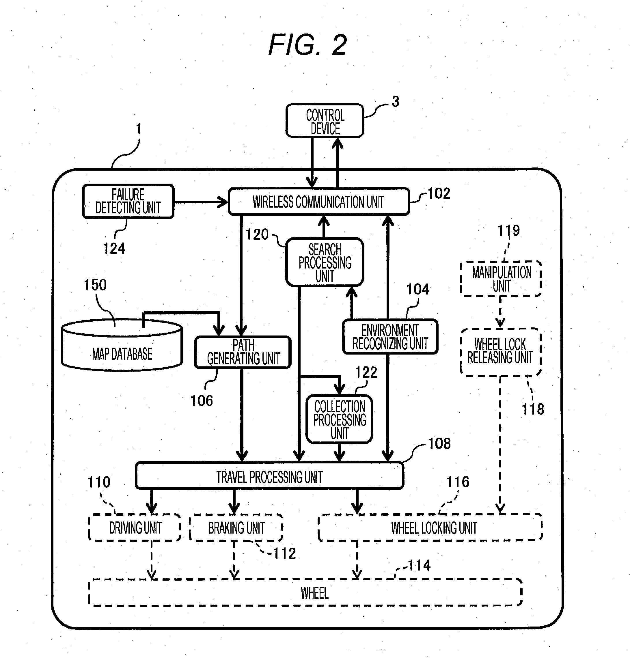
[0139]This embodiment relates to a method of enabling a disabled vehicle to be searched easily by a collection vehicle when a failure part of the disabled vehicle is a wireless communication unit 402 (FIG. 2) in the autonomous movement system 10 according to the first to third embodiments. In the fourth embodiment, because a configuration and a process of the autonomous movement system 10 are the same as those of the first embodiment, the description is omitted.
[0140]FIG. 14 is a diagram illustrating a method of stopping the disabled vehicle according to the fourth embodiment.
[0141]In an autonomous moving apparatus 1, a reflection plate (notifying unit) 450 of a predetermined pattern is attached to an upper portion. The reflection plate 450 turns to the front at the time of normal travel. In addition, even when a failure detecting unit 124 (FIG. 2) detects failure and movement to a r...
PUM
 Abstract
Description
Claims
Application Information