Microelectromechanical device with motion limiters

a technology of motion limiters and microelectromechanical devices, which is applied in the direction of devices using electric/magnetic means, acceleration measurement using interia forces, instruments, etc., can solve the problems of increasing the risk of stiction between the contact surface, the design limit is also at risk, and the motion limiter itself may also break

Active Publication Date: 2015-08-27
MURATA MFG CO LTD
View PDF3 Cites 19 Cited by
  • Summary
  • Abstract
  • Description
  • Claims
  • Application Information

AI Technical Summary

Benefits of technology

[0008]An object of embodiments of the present invention is to provide a compact robust motion limiter configuration for microelectromechanical devices that include a movable mass designed to move out-of-plane of its structural layer. These and other objects of the invention are achieved with a microelectromechanical device as described and claimed herein.

Problems solved by technology

Such an event may occur, for example, when a device is accidentally dropped to the floor on a manufacturing line.
Design limits are also at risk during element testing.
However, the motion limiter itself may also break if it is not robust enough.
However, this increases the risk of stiction between the contacting surfaces.
Efficient motion limiting is especially complicated in structures where a movable mass is designed to undergo out-of-plane linear or rotary motion above or between further structural layers.
It is difficult to create truly robust structure without significantly increasing the size or complexity of the configuration.

Method used


Image

  • Microelectromechanical device with motion limiters
  • Microelectromechanical device with motion limiters
  • Microelectromechanical device with motion limiters

Examples


Embodiment Construction

[0021]The following embodiments are exemplary. Although the specification may refer to “an”, “one”, or “some” embodiment(s), this does not necessarily mean that each such reference is to the same embodiment(s), or that the feature only applies to a single embodiment. Single features of different embodiments may be combined to provide further embodiments.

[0022]In the following, features of the invention will be described with examples of a device architecture in which various embodiments of the invention may be implemented. Only elements relevant for illustrating the embodiments are described in detail. Various implementations of microelectromechanical devices that are generally known to a person skilled in the art may not be specifically described herein.

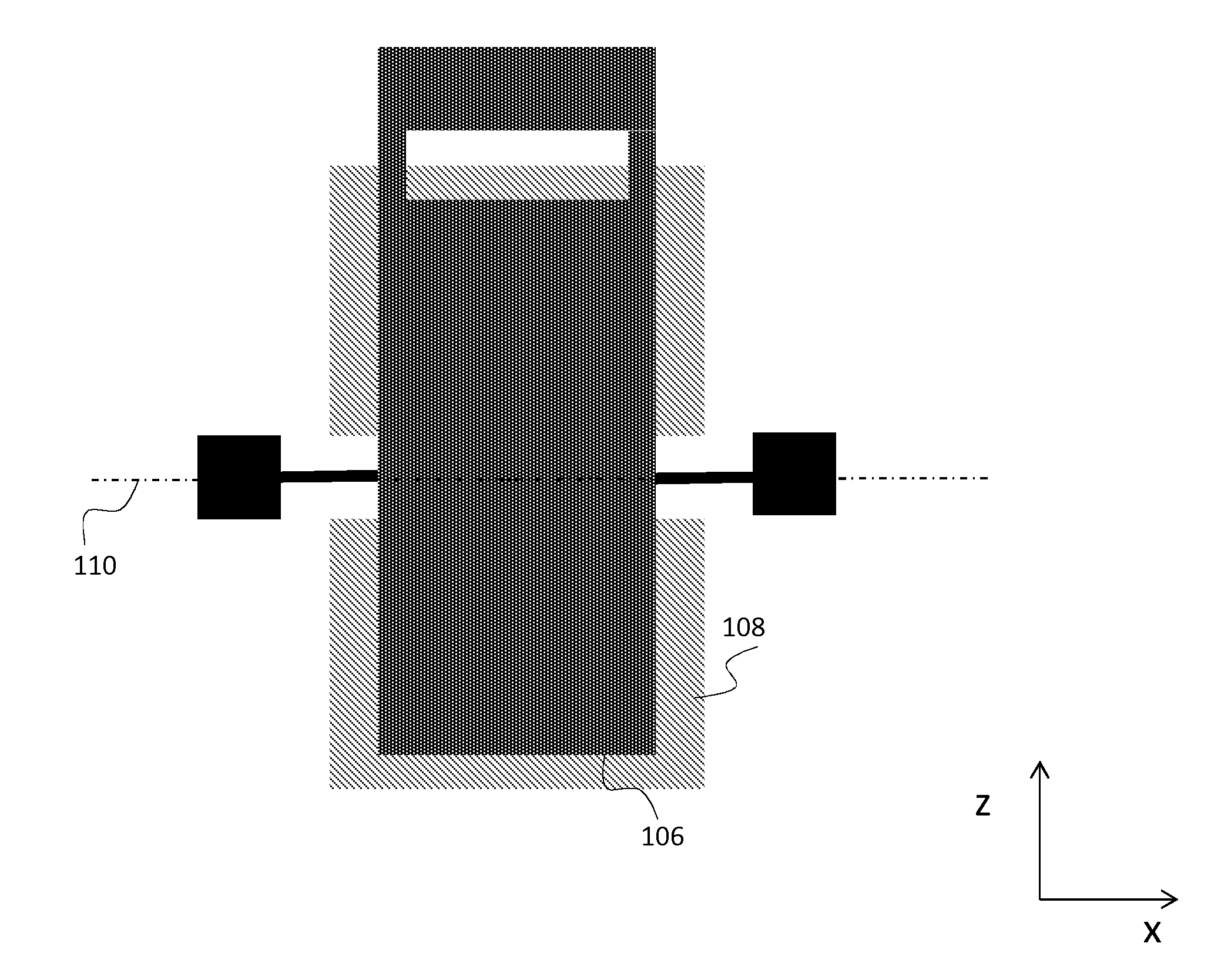
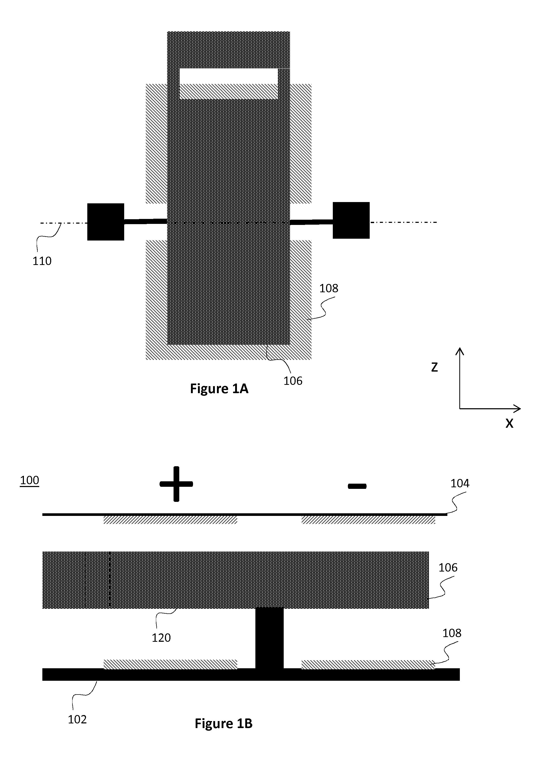
[0023]FIGS. 1A and 1B illustrate an exemplary structure of a microelectromechanical device according to embodiments of the present invention. The microelectromechanical device refers here to a layered structure formed of planar, sol...


PUM


Abstract

A microelectromechanical device that comprises a first structural layer, and a movable mass suspended to a primary out-of plane motion relative the first structural layer. A cantilever motion limiter structure is etched into the movable mass, and a first stopper element is arranged on the first structural layer, opposite to the cantilever motion limiter structure. Improved mechanical robustness is achieved with optimal use of element space.

Description

BACKGROUND[0001]1. Field[0002]The present invention relates to microelectromechanical devices and especially to a microelectromechanical device, as defined in the preamble of the independent claim.[0003]2. Description of the Related Art[0004]Micro-Electro-Mechanical Systems, or MEMS can be defined as miniaturized mechanical and electro-mechanical systems where at least some elements have a mechanical functionality. MEMS devices can be applied to quickly and accurately detect very small changes in physical properties.[0005]Motion limiters are commonly used in MEMS devices to control the maximum distance that a movable structure inside a device can displace. Another purpose for motion limiters is to dissipate energy in a controlled way in case a movable structure collides with an anchored structure inside a device due to a sudden high acceleration event. Such an event may occur, for example, when a device is accidentally dropped to the floor on a manufacturing line. Design limits are ...

Claims


Application Information

Patent Timeline
Patent Type & Authority Applications(United States)
IPC IPC(8): G01C19/5712B81B3/00
CPCB81B3/0051G01C19/5712B81B2201/0235B81B2203/0181B81B2203/058G01P15/125G01P2015/0831G01P2015/0871B81B5/00G01P15/08
Inventor AHTEE, VILLERYTKONEN, VILLE PEKKA
Owner MURATA MFG CO LTD
Why Eureka
Try Eureka