Eureka AIR delivers breakthrough ideas for toughest innovation challenges, trusted by R&D personnel around the world.

Electric connector attachment structure of battery pack for electric vehicle

a technology of electric vehicles and attachment structures, which is applied in the direction of batteries/cells, cell components, battery pack installation space restrictions, etc., can solve the problems of reducing the capacity (volume) of the tray, and requiring increasing the size of the tray. , to achieve the effect of not reducing the inclination angle of the inclined portion

Active Publication Date: 2015-08-27
MITSUBISHI MOTORS CORP
View PDF4 Cites 21 Cited by
  • Summary
  • Abstract
  • Description
  • Claims
  • Application Information

AI Technical Summary

Benefits of technology

The patent text describes a problem with the installation of battery packs in sports electric vehicles or small-sized electric vehicles. Ground clearance is often limited, which makes it difficult to install the battery pack. This also results in a low height for the battery pack, which affects the arrangement of electric devices and the length of the electrical cable. When the inclination angle of the battery pack is reduced, the area occupied by the battery pack is increased, which reduces the capacity of the battery pack and requires a larger tray. This patent aims to solve these issues by proposing a new design for the installation of battery packs in electric vehicles.

Problems solved by technology

However, especially in a case of a sporty electric vehicle or a small-sized electric vehicle, the ground clearance tends to be set low, which further restricts the installation space of the battery pack.
Further, when the inclination angle of the inclined portion is reduced, the area of the tray occupied by the inclined portion increases, which reduces the capacity (volume) of the tray and requires increasing the size of the tray in a vehicle front-rear direction or a vehicle width direction.

Method used


Image

  • Electric connector attachment structure of battery pack for electric vehicle
  • Electric connector attachment structure of battery pack for electric vehicle
  • Electric connector attachment structure of battery pack for electric vehicle

Examples


Embodiment Construction

[0023]An electric-connector attachment structure of a battery pack for an electric vehicle according to one embodiment of the present invention will be described in detail referring to the accompanying drawings. The invention is not limited to the embodiment described below.

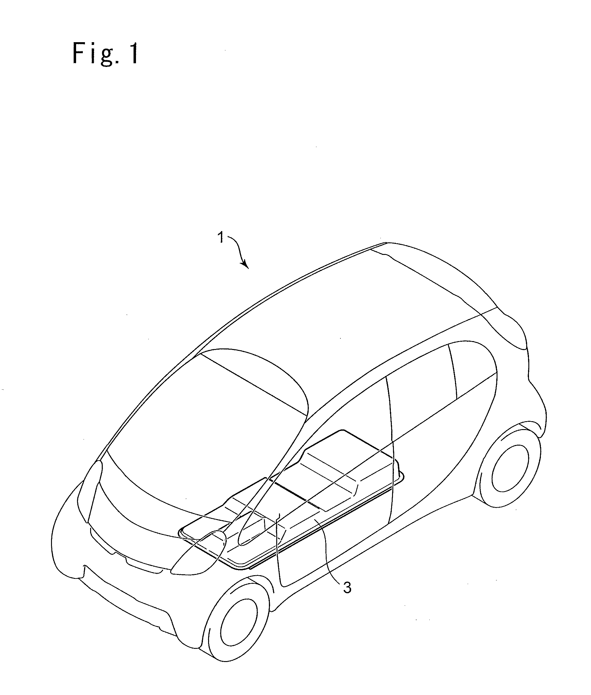
[0024]FIG. 1 is a schematic diagram of an electric vehicle equipped with an electric-connector attachment structure of a battery pack for an electric vehicle according to an embodiment of the present invention. Hereinafter, an electric-connector attachment structure of a battery pack for an electric vehicle mounted to a small-size electric vehicle will be described as an example. The present invention, however, is not limited to this and is applicable to general electric vehicles including sporty electric vehicles.

[0025]As illustrated in FIG. 1, an electric-connector attachment structure of a battery pack for an electric vehicle according to an embodiment of the present invention is to supply electric power to an...


PUM


Abstract

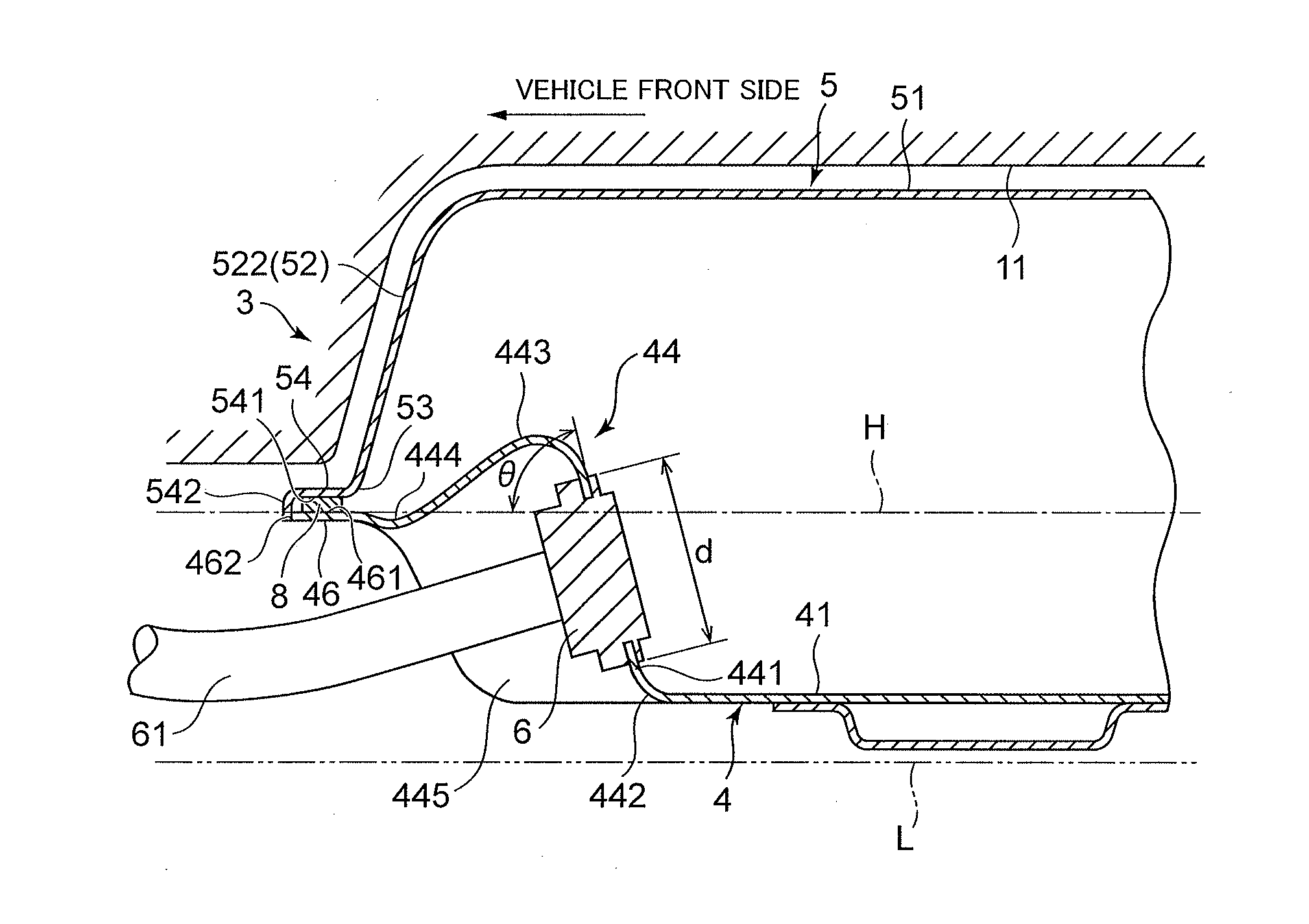
To provide an electric-connector attachment structure of a battery pack for an electric vehicle, which can attach an electric connector to a battery pack even when the height of the battery pack for an electric-vehicle is set low, the electric-connector attachment structure includes: a battery pack 3 for an electric vehicle including a tray 4 of a box-like shape which accommodates a battery and has an opening on an upper side, and a cover 5 of a box-like shape having an opening on a lower side, the tray 4 and the cover 5 being joined at a horizontal plane; and an electric connector 6 to which an electrical cable 61 is connected. It further includes an inclined portion 441, 551 to which the electric connector 6 is connected, disposed at an inner side of the battery pack 3 with respect to a joint surface 461 at which the tray 4 and the cover 5 are joined, extending over lower and upper regions across the horizontal plane H passing through the joint surface 461; and a protruding portion 443, 553 disposed between the joint surface 461 and the inclined portion 441, 551 so as to protrude from the horizontal plane passing through the joint surface 461 in a direction opposite to the electric connector 6. The inclined portion 441, 551 is formed so as to be continuous from the protruding portion 443, 551.

Description

TECHNICAL FIELD[0001]The present disclosure relates to an electric-connector attachment structure of a battery pack for an electric vehicle, and more specifically, to an attachment structure that can attach an electric connector even in a case where the height of a battery pack for an electric vehicle is sot low.BACKGROUND[0002]A battery pack for an electric vehicle is to supply electric power to an electric drive mounted on an electric vehicle, and is disposed in a lower region of a floor panel. The battery pack includes a tray and a cover. An electric connector (charge connector) for charging a battery pack with electric power and an electric connector (supply connector) for supplying electric power to an electric drive from the battery pack are attached to a lateral face of the tray.[0003]Meanwhile, the size of each electric connector (the charge connector and the supply connector) is determined depending on the electric capacitance of the electric power flowing through the elect...

Claims


Application Information

Patent Timeline
IPC IPC(8): H01M2/30H01M2/10H01M50/209H01M50/249H01M50/271
CPCH01M2/305H01M2220/20H01M2/1083Y02T10/7072Y02T90/14B60L53/16B60L50/66B60L50/64Y02T10/70Y02E60/10H01M50/249H01M50/209H01M50/271
Inventor LOO, WENG LEONGTAKASAKI, SEIICHI
Owner MITSUBISHI MOTORS CORP
Why Eureka
Eureka Blog
Learn More