Electronic component mounting apparatus and electronic component mounting method

a technology for mounting apparatuses and electronic components, applied in the direction of soldering apparatuses, manufacturing tools,auxillary welding devices, etc., can solve the problems of increased production time and complicated structure, and achieve the effect of enhancing productivity, facilitating processing, and facilitating assembly

Active Publication Date: 2015-08-27
JUKI CORP
View PDF2 Cites 29 Cited by
  • Summary
  • Abstract
  • Description
  • Claims
  • Application Information

AI Technical Summary

Benefits of technology

[0019]The invention provides an effect that images can be processed efficiently, el

Problems solved by technology

However, in order to photograph the images of a substrate and electronic parts being sucked by cameras not provided on a head, another camera moving mechanism is necessary, resulti

Method used


Image

  • Electronic component mounting apparatus and electronic component mounting method
  • Electronic component mounting apparatus and electronic component mounting method
  • Electronic component mounting apparatus and electronic component mounting method

Examples


Embodiment Construction

[0036]Description is given below specifically of the invention with reference to the drawings. Here, the invention is not limited to the mode for carrying out the invention (which is hereinafter called an embodiment). Also, the composing elements of the embodiment contain elements easily assumable by persons skilled in the art, the substantially same elements and the elements that fall within a so-called equivalent range. Further, the composing elements disclosed in the following embodiment can be combined properly.

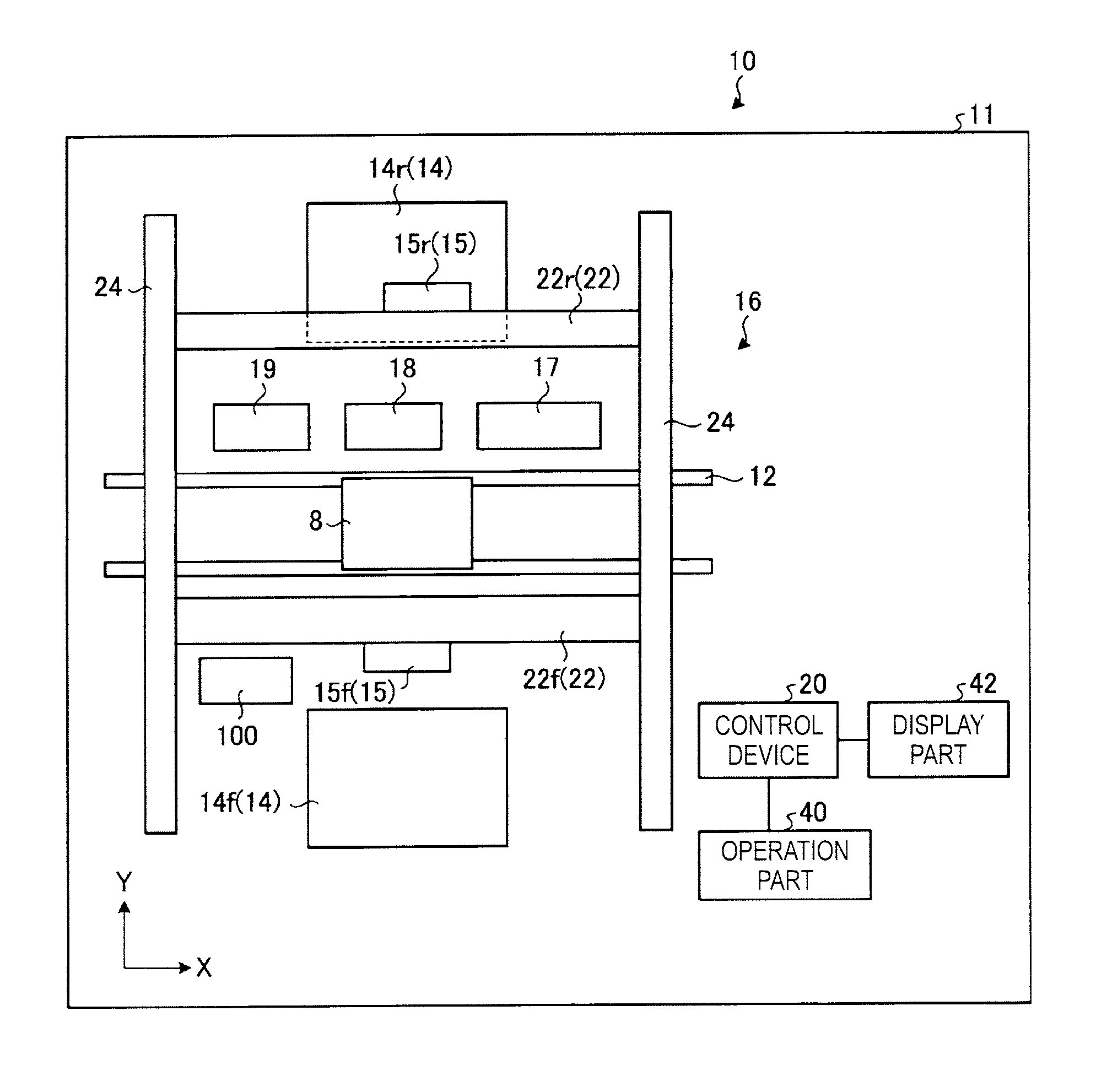
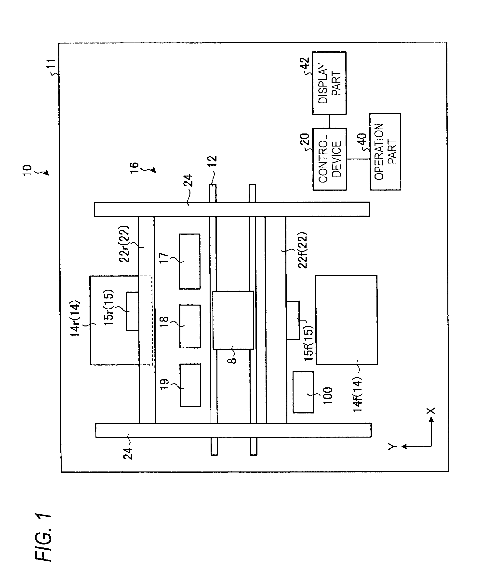
[0037]Description is given below specifically of the embodiment of the electronic component mounting apparatus of the invention with reference to the drawings. Here, the invention is not limited to this embodiment. This embodiment provides an electronic component mounting apparatus which includes a lead wire (insertion part) and is capable of mounting an electronic component, namely, a so-called insertion type electronic component to be mounted onto a substrate by inserti...


PUM

PropertyMeasurementUnit
Areaaaaaaaaaaa

Abstract

An electronic component mounting apparatus includes an electronic component supply device for supplying an electronic component, a head including a head main body and a head camera unit, and a control device. The head main body includes nozzles, a nozzle drive unit for driving the nozzles and a head support body for supporting the nozzles and the nozzle drive unit. The head camera unit is fixed to the head support body and has head cameras corresponding to the nozzles respectively for photographing electronic components. The head drives the nozzles to hold the electronic components, transfers the electronic components from the electronic component supply device to the substrate and mounts the electronic components onto the substrate. The control device synthesizes images photographed by the head cameras to generate an image with fields of the head cameras connected together, and determines a process based on the synthesized image synthesized.

Description

CROSS-REFERENCE TO RELATED APPLICATIONS[0001]This application is based upon and claims the benefit of priority from Japanese Patent Application No. 2014-035935, filed on Feb. 26, 2014; the entire contents of which are incorporated herein by reference.BACKGROUND OF INVENTION[0002]1. Field of the Invention[0003]The invention relates to apparatus and method for mounting an electronic component onto a substrate.[0004]2. Related Art[0005]An electronic component mounting apparatus repeats an operation to hold an electronic component using a nozzle provided on a head and mount it onto a mounting point provided at a substrate to thereby mount electronic components onto the substrate. Some of this type electronic component mounting apparatus includes an imaging device for photographing an area to be checked in order to check and observe the state of the substrate and the state of electronic components to be mounted. For example, JP-U-3165153 discloses a camera used to check whether a bad mar...

Claims


Application Information

Patent Timeline
IPC IPC(8): H05K13/02H05K3/30B23K31/12H05K13/08B23K3/08B23K37/04H05K3/32H05K13/04
CPCH05K13/022H05K3/32H05K3/303H05K13/046H05K13/08H05K2203/30B23K37/04B23K31/12H05K2203/15H05K2203/163H05K2203/166B23K3/082H05K13/0812
Inventor KURITA, NAOKIOOHASHI, TAKAHIROIMASU, TAKAHIKOKOBAYASHI, KOUEISAKATA, YASUAKI
Owner JUKI CORP
Why Eureka
Try Eureka