Capacitive input device

Active Publication Date: 2015-09-03
ALPS ALPINE CO LTD
View PDF12 Cites 6 Cited by
  • Summary
  • Abstract
  • Description
  • Claims
  • Application Information

AI Technical Summary

Benefits of technology

[0021]In the present invention, the detection electrode portions are arranged on both sides of the plurality of driving electrode portions, such that an approach state and an approach position of the operation body that has approached the front of the electrode groups can be detected with high prec

Problems solved by technology

Further, since an operation of sequentially switching the combination between the detection line and the driving line to all of the X l

Method used


Image

  • Capacitive input device
  • Capacitive input device
  • Capacitive input device

Examples


Embodiment Construction

Structure of Capacitive Input Device

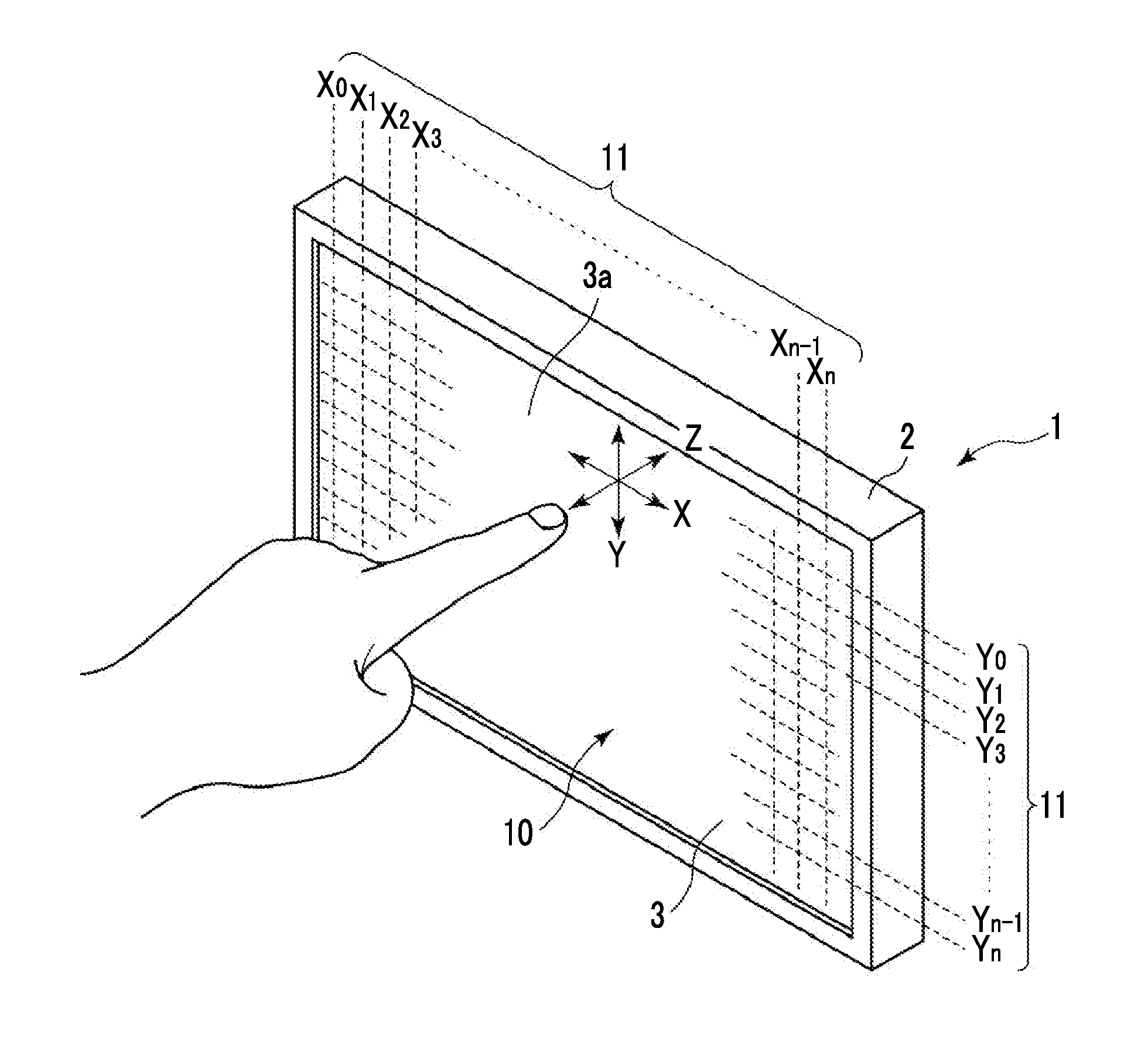
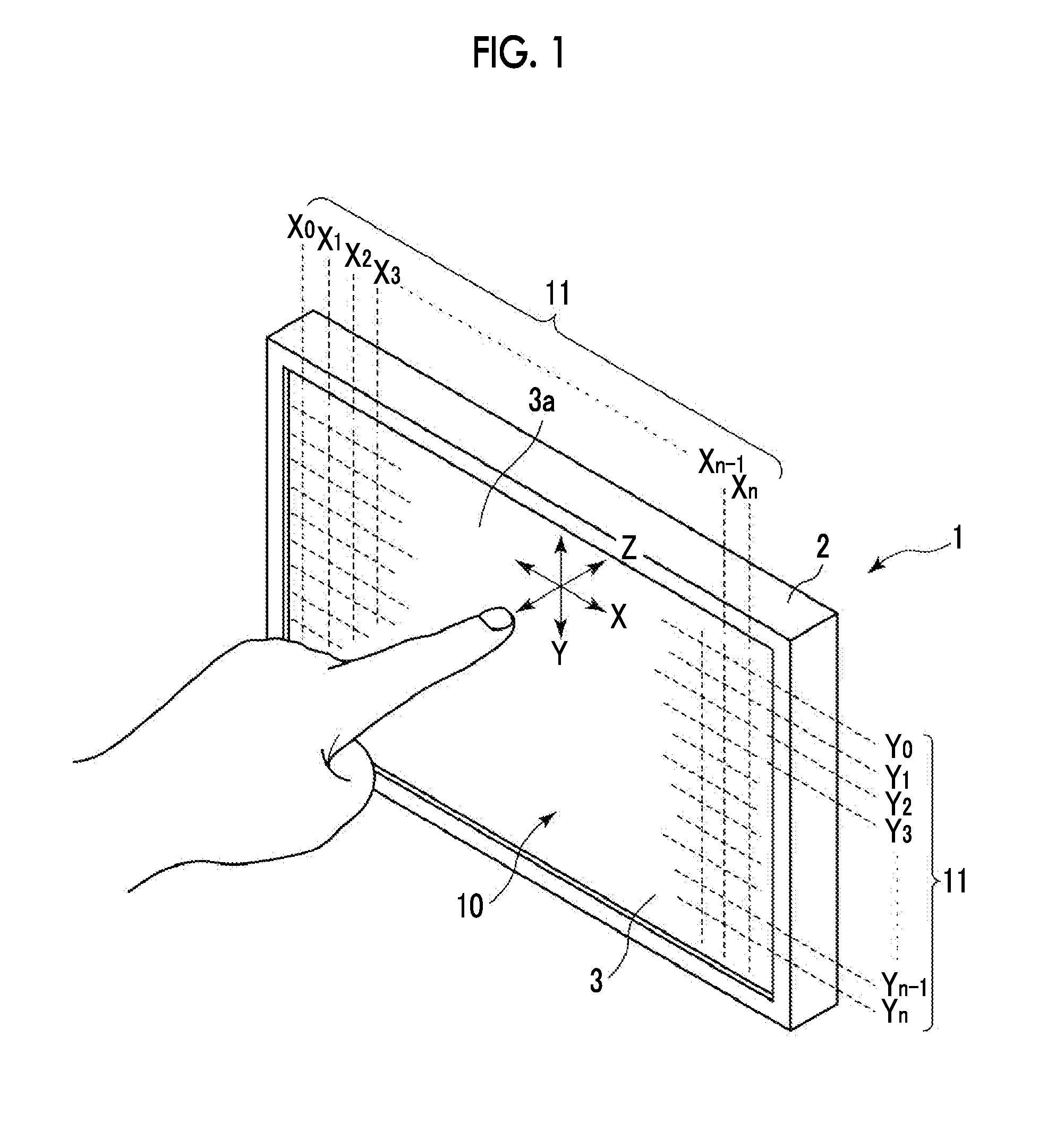
[0028]In a display input device 1 illustrated in FIG. 1, a display device 3 such as a color liquid crystal display panel is provided inside a housing 2, and a capacitive input device 10 with a light transmission characteristic is arranged in front of the display device 3.

[0029]When the display input device 1 is used for a vehicle, car navigation information, audio system information, radio reception information, road information, setting information of an air conditioner, or other information on driving or facility of the vehicle is displayed on a display screen 3a of the display device 3.

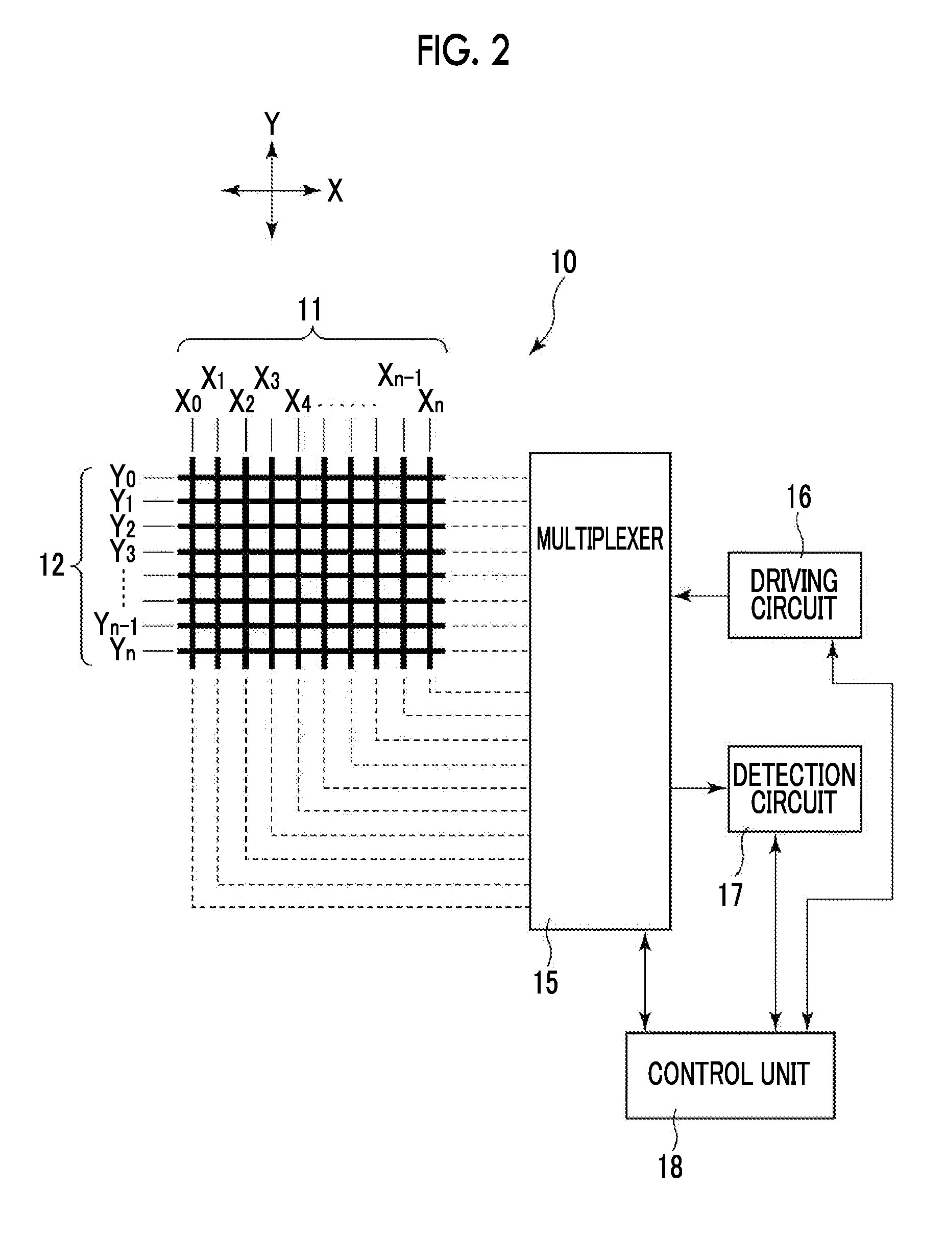
[0030]In the capacitive input device 10 illustrated in FIGS. 1 and 2, an X direction is a first direction, a Y direction is a second direction, and a Z direction is a front and back direction (approaching and separating direction).

[0031]A first electrode group 11 and a second electrode group 12 are provided in the capacitive input device 10. In FIG. 3, a cross-se...


PUM


Abstract

Electrode portions located on both ends are set to detection electrode portions, ground electrode portions are set on the inside thereof, and a plurality of central electrode portions are set to driving detection portions. A coordinate position of a finger can be obtained based on an output difference between the detection electrode portions, and a vertical distance can be obtained based on an output sum. When the vertical distance of the finger is shorter than a first threshold, switching is performed so that an interval between the detection electrode portions is shortened, and when the finger approaches, a touch detection mode is set.

Description

CLAIM OF PRIORITY[0001]This application claims benefit of Japanese Patent Application No. 2014-040891 filed on Mar. 3, 2014, which is hereby incorporated by reference.BACKGROUND OF THE INVENTION[0002]1. Field of the Invention[0003]The present invention relates to a capacitive input device that detects a position of an operation body such as a finger or a hand located in front of an electrode group having a plurality of electrode portions.[0004]2. Description of the Related Art[0005]Japanese Unexamined Patent Application Publication No. 2013-80290 discloses an invention of a touch sensor that enables so-called hover detection. The hover detection is also called hovering detection and refers to a detection operation of detecting presence of a finger or a hand in a position away from an operation surface of a touch sensor and a position thereof.[0006]The touch sensor described in Japanese Unexamined Patent Application Publication No. 2013-80290 selects three lines of a plurality of lin...

Claims


Application Information

Patent Timeline
IPC IPC(8): G06F3/044G06F3/041H03K17/96
CPCG06F3/044H03K17/9622G06F3/0416G06F2203/04101H03K2217/960745H03K2217/960755G06F2203/04112H03K2017/9613G06F3/04166G06F3/0446
Inventor WAKUDA, HIROSHI
Owner ALPS ALPINE CO LTD
Why Eureka
Try Eureka