

Face shield
a technology for protecting the face and the face, applied in the field of face shields, can solve the problems of ineffective sunscreen, increased discomfort, and increased discomfort of sunbathers,
- Summary
- Abstract
- Description
- Claims
- Application Information
AI Technical Summary
Benefits of technology
Problems solved by technology
Method used
Image

Examples
first embodiment
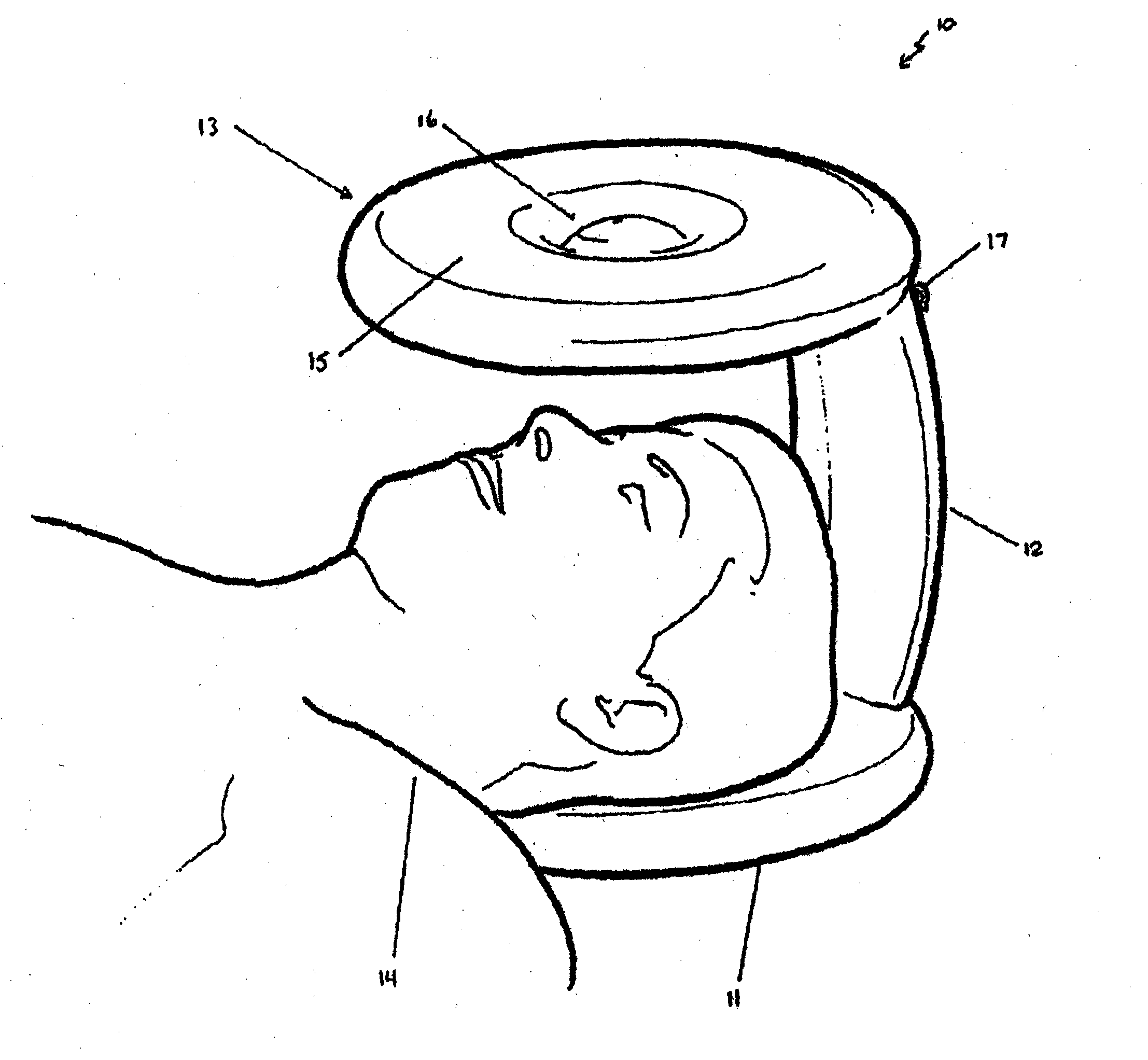
[0046]The face shield 10 shown in FIG. 1 is a first particular embodiment of the invention. The face shield of the first embodiment comprises a base member 11, an upstanding member 12 and a shade member 13. The face shield 10 is shown with a user 14 in position with their head placed on the base member 11 and shielded from sun by the shade member 13.
[0047]Both the base member 11 and the shade member 13 are substantially similar in this embodiment as the user 14 can then use the face shield in either orientation without sacrificing protection or comfort. The structure of both the base member 11 and the shade member 13 are described with reference to the shade member 13.
[0048]The shade member 13 is substantially circular in shape when viewed from above. The shade member 13 has an enlarged outer annular shaped portion 15 and a thinner central portion 16. The enlarged outer annular shaped portion 15 is inflatable. The thinner central portion 16 may be inflatable but need not be. Indeed,...
second embodiment
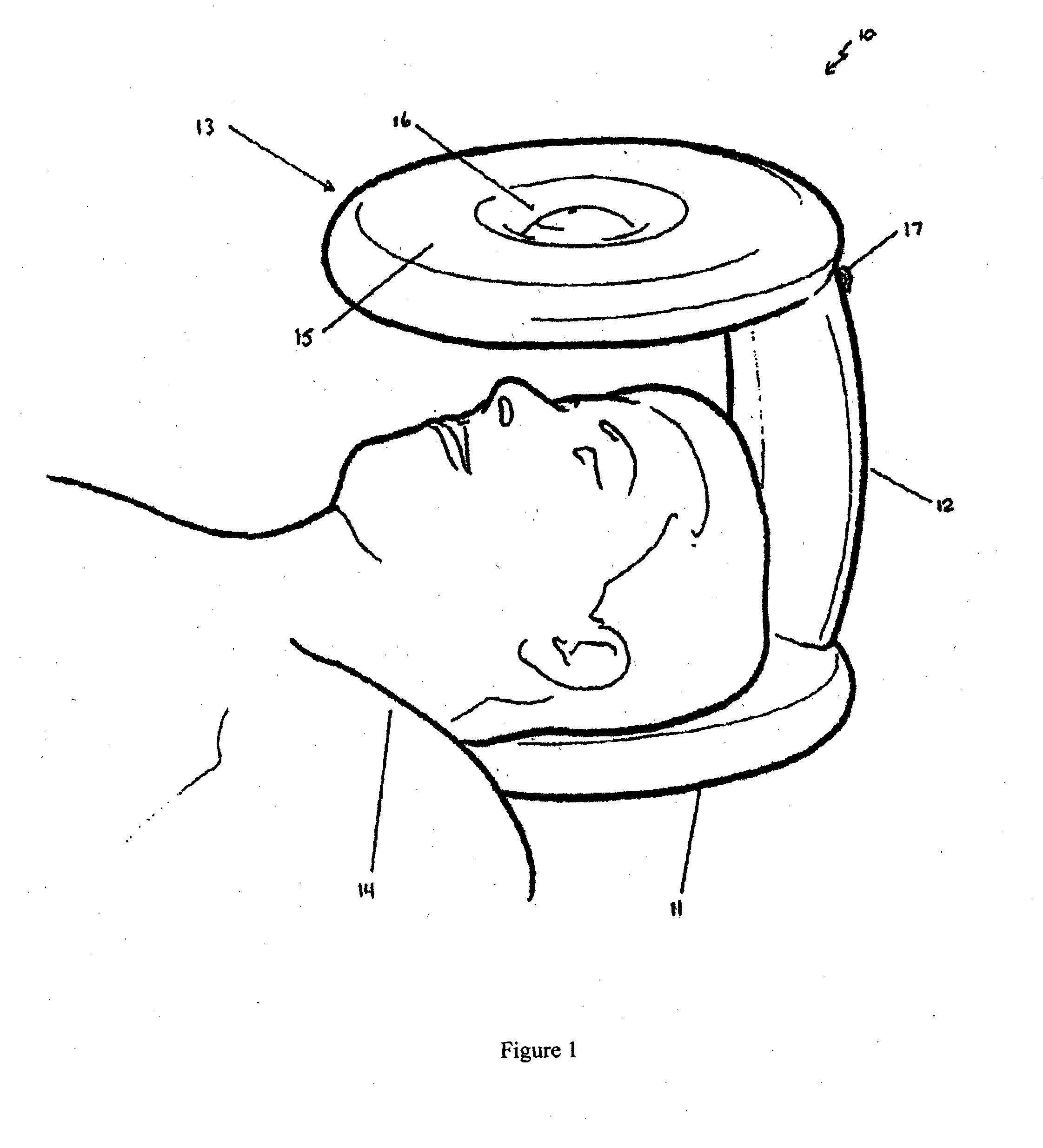
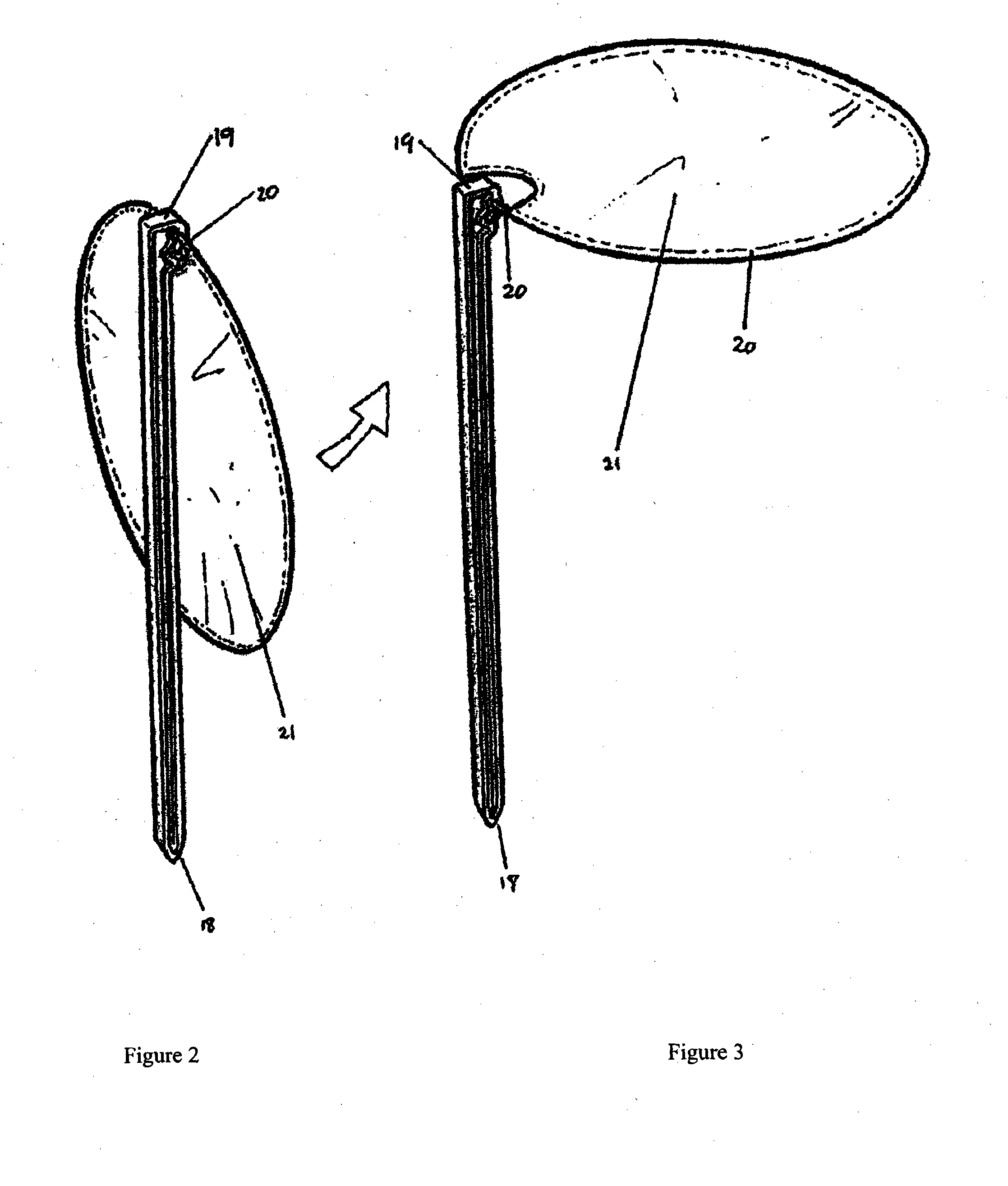
[0051]According to the invention shown, in FIGS. 2 and 3, the face shield 10 has an elongate upstanding member 12 having a sharpened or pointed lower end 18 adapted for insertion into the ground. The upstanding member 12 also has a flattened upper end 19 adapted for the application of a force thereto, in order to force or drive the lower end 18 of the upstanding member 12 into the ground.
[0052]The shade member as shown in FIGS. 2 and 3 is shown as a substantially circular frame member 20 with ultraviolet impermeable fabric 21 associated with the frame member 20. The shade member is rotatably mounted adjacent the upper end of the upstanding member 12. The shade member can be moved from the travel position or stored position shown in FIG. 2 into the shade position or use position shown in FIG. 3. According to this embodiment of the upstanding member 12 may be manufactured from a lightweight but strong and rigid plastic material, and the frame member 20 is manufactured from a lightweig...
third embodiment
[0053]According to the invention shown in FIG. 4, the base member 11 and the shade member 13 are again substantially similar. According to this embodiment, both the base member 11 and the shade member comprise a substantially circular frame member 20 with ultraviolet impermeable fabric 21 associated with the frame member 20. The upstanding member in this embodiment comprises a rigid lightweight member 22 extending diagonally or helically between the base member 11 and the shade member 13 and maintaining the spacing between them. The lightweight diagonal member 22 also provides additional support for an upstanding member comprising two substantially vertical frame members 23 with a portion of ultraviolet impermeable fabric 21 secured to and extending between the frame members 23.
[0054]The particular embodiment shown in FIG. 4 also comprises a peg member 24 secured to the frame member 20 of the base member 11 by a length of wire or string 25 or the like. The peg member 24 is adapted t...
PUM
 Abstract
Description
Claims
Application Information