Footwear Sole Structure with Suspended Elastomeric Web or Mesh Support

a technology of elastomeric web and shoe sole, which is applied in the field of shoe sole structure with suspended elastomeric web or mesh support, to achieve the effects of reducing the energy exerted by the wearer, accentuating the comfort of the shoe, and softening the pressure applied

Inactive Publication Date: 2015-09-10
ATTEY GRAEME SCOTT +1
View PDF24 Cites 26 Cited by
  • Summary
  • Abstract
  • Description
  • Claims
  • Application Information

AI Technical Summary

Benefits of technology

[0014]The suspended elastomeric web / mesh footwear is able to provide superb ventilation as the open mesh design allows the majority of the foot to breathe due to the low surface area physical contact with the web / mesh.
[0015]It is most important to understand that the web / mesh elastomer not only offers comfort and ventilation but critically eases pressure on limbs such as ankles and knees. Because the mesh is a flexible elastic / elastomer material it flexes and rebounds gently to ease the impact pressure on knees, ankles etc.
[0018]It is therefore possible to also include soft foam in at least some of this space or gap. The web / mesh can therefore touch the foam if forced down far enough, which in turn can soften the pressure applied to the bottom of the sole. Importantly, although the web / mesh has ‘bottomed out’ it has still absorbed a large part of the downward force and impact in the process and can in turn rebound a percentage of this force as the web / mesh returns to a more normal position. In fact, the rebound is the most immediately noticeable characteristic of the footwear. This can effectively reduce the energy exerted by the wearer, particularly if climbing stairs etc.
[0019]In such instances of high load, because the web has absorbed a large percentage of the initial load, it means the foam can be softer than usual (on a normal shoe, the foam must take the FULL load) further accentuating the comfort of the shoe.

Problems solved by technology

However, all these approaches are still based on compression of the cushioning material.

Method used


Image

  • Footwear Sole Structure with Suspended Elastomeric Web or Mesh Support
  • Footwear Sole Structure with Suspended Elastomeric Web or Mesh Support
  • Footwear Sole Structure with Suspended Elastomeric Web or Mesh Support

Examples


first embodiment

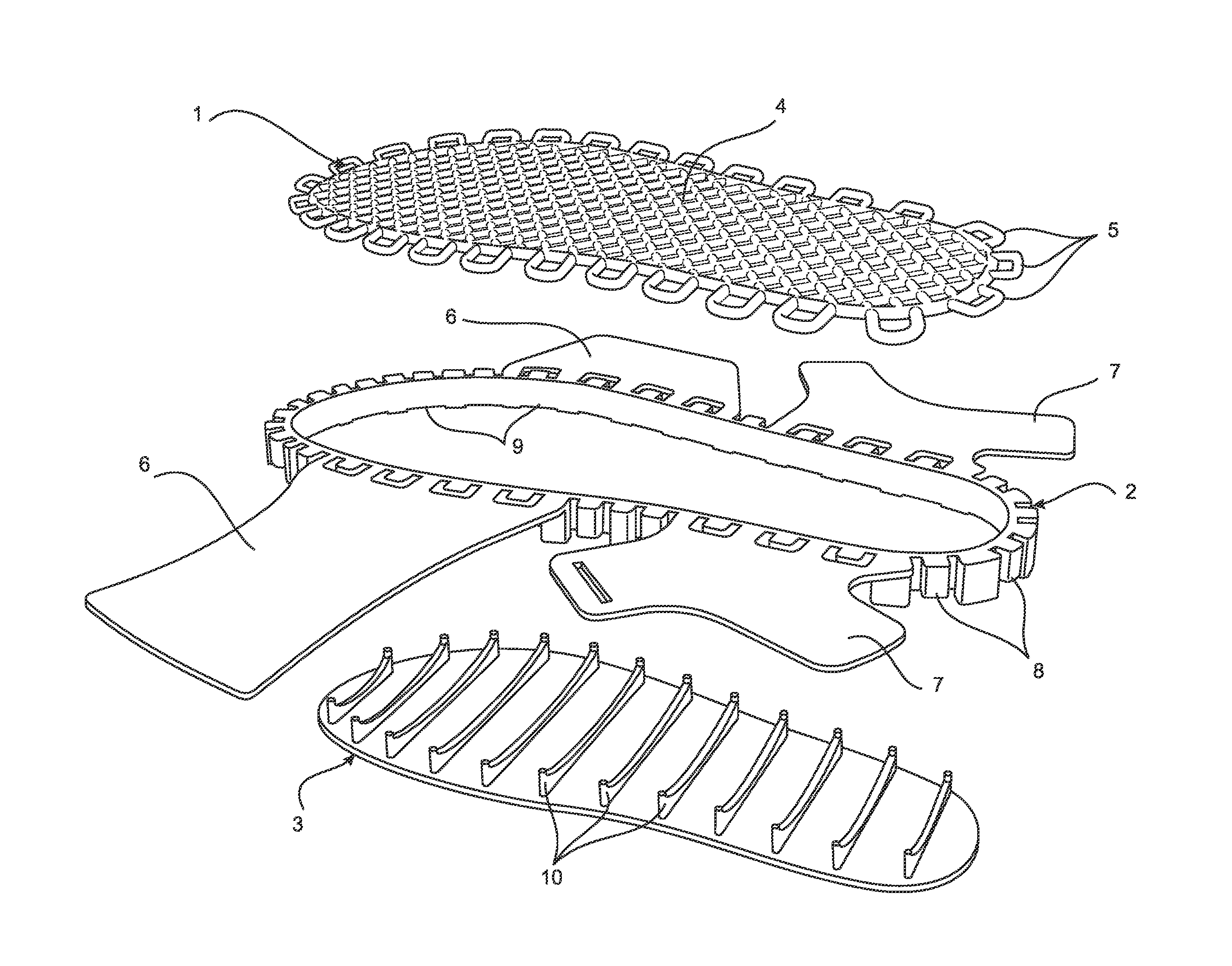
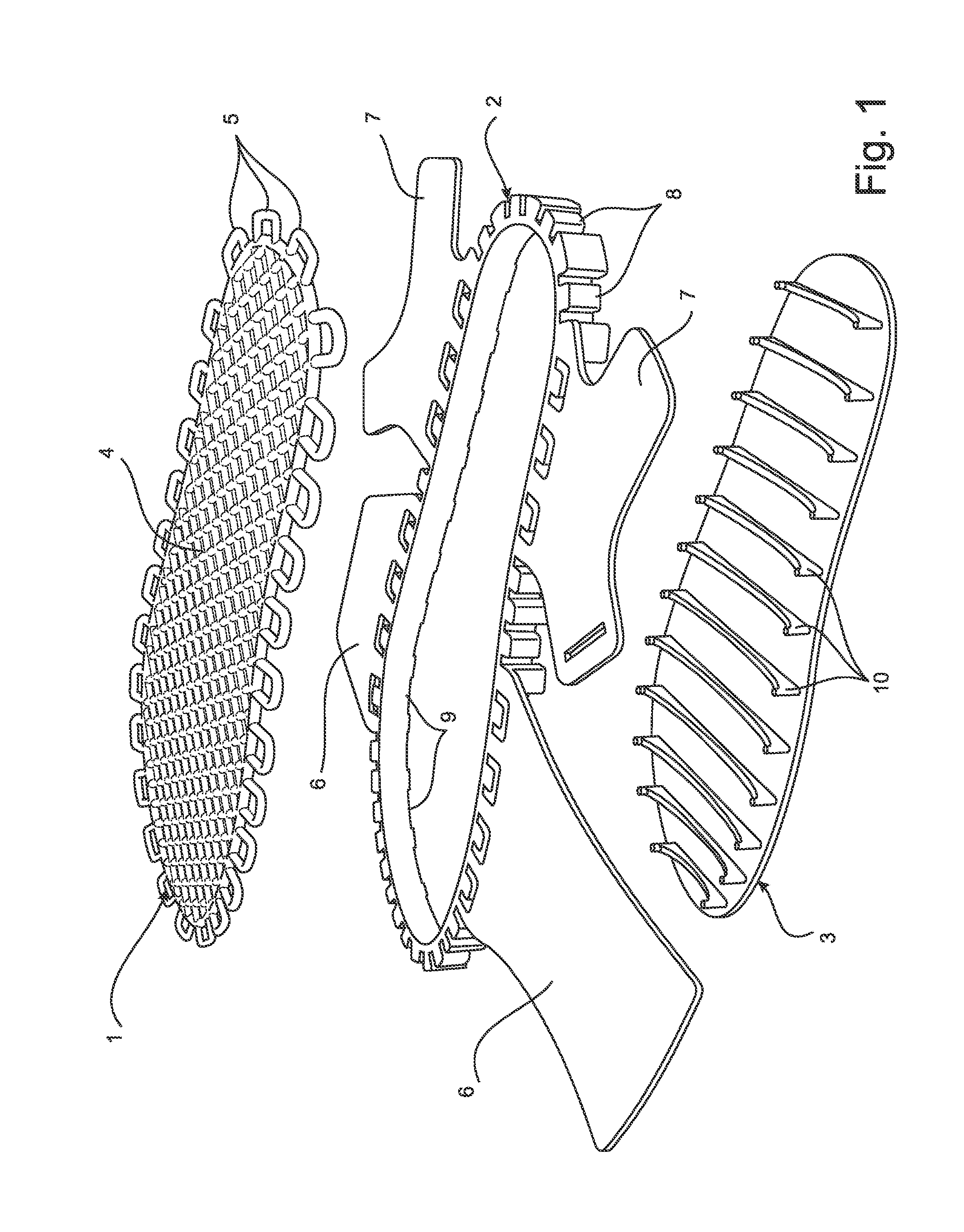
[0062]FIG. 1 is an example of the footwear embodying the present invention as described above, being a rear angled perspective view of the three main components:[0063](a) at the top, a typical elastomer web / mesh 1 in a diagonal grid style pattern 4 and with outer connection loops 5,[0064](b) in the middle, the central body 2 being a single part moulding incorporating a front strap pair6, rear strap pair 7, lugs 8 and inner lip 9, and[0065](c) at the bottom, the higher density elastomer sole 3 featuring curved cross-brace supports 10; wherein the higher density sole 3 fits up and is bonded (or even moulded together as one part) into a matching lip 9 in the base of the central body 2 (see upwards direction arrows) and the elastomer web 1 fits down over the central body 2 such that the web loops 5 stretch around corresponding lugs 8 on the central body 2 (see downward direction arrows) such that the web / mesh 1 is largely held in pre-tension via the supports 10 and there is still space ...

second embodiment

[0072]FIG. 5 is an example of the structure described, being a side view of a structure showing a higher density elastomer cover / outer 30 fitted with a web or mesh supporting system consisting of (on each side of the shoe) ‘comb’ structures 28, the bottom sections of which incorporate ‘teeth’24 which insert into matching slots in the cover / outer 30 and the top sections of which hold the web or mesh 20 end loops 22. When the comb 28 teeth 24 are inserted into the cover / outer 30 the web or mesh 20 is stretched across from side to side and held in position and under pre-tension via the end loops 22 hooked over the top lugs of the comb 28 supports.

[0073]FIG. 6 is an example of the same second embodiment of the Web-Shoe described in FIG. 5, being three exploded cross-sectional explanatory views of the structure in FIG. 5 showing a higher density elastomer cover / outer 30 fitted with a Web supporting system on each side of the cover / outer 30 consisting of ‘comb’ structures 28, the bottom s...

third embodiment

[0074]FIG. 7 is an example of the structure described, being three side views and two cross-sections of a system 40. The top side view shows the complete system 40 and the two side views below that show detailed section side views of an H-Section mid-section 48 incorporating mesh 20 throughout the middle with vertical edge sections around the periphery that incorporate peg holes 42. Also shown is the higher density elastomer sole 44 that incorporates the U-shaped metal or stiff wire pegs 46. The horizontal sections of the pegs 46 provide lateral stiffness to permit the web or mesh 20 to be pre-stretched and the vertical sections of the pegs 46 slot into matching recess peg holes 42 in the H-section 48 above it.

[0075]FIGS. 8 and 8A show an example of a fourth and simplest embodiment of the structure described, being an exploded perspective view (FIG. 8) and top / plan view (FIG. 8A) of the two main parts of the lower shoe section of a Web-Shoe. The section 90 is the single piece moulde...


PUM


Abstract

A footwear sole structure has a suspended elastomer web or mesh (1) support for a foot of a wearer of the footwear. A gap or space under the web / mesh allows it to flex down e.g. towards the outsole (3) or the ground. The web or mesh can be secured to a peripheral portion of the sole base by projections or loops (5) on the web or mesh. The web or mesh can be a one piece or multi part moulded component. The web or mesh can provide a peripheral zone around a central zone. The central body (2) can be a moulding incorporating a front strap pair (6) and rear strap pair (7) folded up into a wearing position and lugs (8), and have a higher density elastomer sole that fits up and is bonded into a matching lip in the base of the central body (2) and the elastomer web or mesh (1) fits down over the central body (2) such that the loops (5) stretch around corresponding lugs (8) on the central body (2) and the web or mesh (1) is largely held in pre-tension via the strength of the sole supports and there is still space between the web or mesh 1 and the sole for the web / mesh (1) to flex down into via weight of foot.

Description

FIELD OF THE INVENTION[0001]The present invention relates to footwear, such as shoes, boots and sandals.BACKGROUND TO THE INVENTION[0002]Conventional footwear consists of an outer sole (outsole) for contact with the ground and an inner sole (insole) for cushioning the user's foot.[0003]Enclosed footwear, such as shoes and boots also have an upper to enclose and position the foot.[0004]For the sake of clarity, in this specification the term ‘footwear’ relates to outer footwear, such as shoes, boots, sandals and does not include items of fabric clothing worn on the feet, such as socks, stockings, tights and pantyhose.[0005]Known footwear by way of conventional shoes consists of cushioned soles to provide comfort. However, no matter what the design or construction method of conventional soles, they are all based on the principle of compression cushioning. In other words, when the weight of a foot is applied to the sole, the cushioning by way of traditional foam material is compressed b...

Claims


Application Information

Patent Timeline
Patent Type & Authority Applications(United States)
IPC IPC(8): A43B13/12A43B5/06A43B3/12A43B13/42A43B13/28
CPCA43B13/125A43B13/42A43B5/06A43B3/128A43B13/28A43B3/108A43B13/14A43B13/181A43B13/185
Inventor ATTEY, GRAEME SCOTTLIN, CADMUS
Owner ATTEY GRAEME SCOTT
Why Eureka
Try Eureka