A Shock Valve Realizing Stepless Pressure

A buffer valve and pressure technology, which is applied in the field of buffer valves, can solve the problems of increased energy consumption, reduced volumetric efficiency of closed hydraulic system, and reduced total efficiency of closed hydraulic system, so as to relieve pressure shock and improve overall efficiency.

Active Publication Date: 2022-06-24
LIYUAN HYDRAULIC (SUZHOU) CO LTD
View PDF5 Cites 0 Cited by
  • Summary
  • Abstract
  • Description
  • Claims
  • Application Information

AI Technical Summary

Problems solved by technology

In a closed hydraulic system, a sudden change in the output flow of the main pump will force a sudden change in the rotational speed of the load motor. Due to the inertia of the load, a high pressure shock is likely to occur in the system. The existing technology sacrifices the volumetric efficiency of the main pump. Suppress pressure shock, but this will seriously reduce the volumetric efficiency of the closed hydraulic system, which also reduces the overall efficiency of the closed hydraulic system and increases energy consumption

Method used


Image

  • A Shock Valve Realizing Stepless Pressure
  • A Shock Valve Realizing Stepless Pressure
  • A Shock Valve Realizing Stepless Pressure

Examples


Embodiment Construction

[0025] The present invention will be further described below in conjunction with the accompanying drawings and embodiments, but not as a basis for limiting the present invention.

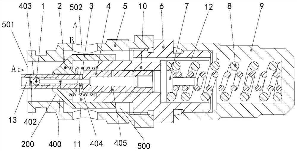
[0026] Example. A shock valve that realizes stepless pressure, such as figure 1 As shown, it includes steel ball 1, main valve core 2, first spring 3, sliding valve core 4, valve body 5, pilot valve seat 6, spring seat 7, second spring 8, screw sleeve 9 and sliding valve sleeve 10;

[0027] The valve body 5 is tubular, and the valve body 5 is provided with a stepped hole 500. The small end of the valve body 5 corresponding to the stepped hole 500 is provided with a first oil inlet and outlet port 501. There is a second oil inlet and outlet 502 on it;

[0028] The main valve core 2 is located in the stepped hole 500, the end of the main valve core 2 facing the small end of the stepped hole 500 is provided with a conical surface 200, and the end surface area of ​​the main valve core 2 in the stepped...


PUM


Abstract

The invention discloses a buffer valve for realizing stepless pressure, which comprises a steel ball, a main valve core, a first spring, a sliding valve core, a valve body, a pilot valve seat, a spring seat, a second spring, a screw sleeve and a sliding valve sleeve The valve body is tubular, with a step hole in the valve body, a first oil inlet and outlet on the small end of the valve body corresponding to the step hole, and a second oil inlet and outlet on the side wall of the valve body corresponding to the big end of the step hole The main spool is located in the step hole, and the end of the main spool toward the small end of the step hole is provided with a conical surface; the sliding spool is a stepped shaft, and the small end of the sliding spool passes through the main spool, and the sliding valve The big end of the spool is inserted into the sliding valve sleeve, a variable throttle opening is formed between the sliding spool and the main spool, and a first oil passage is arranged inside the sliding spool. The invention can alleviate the pressure shock without sacrificing the volumetric efficiency of the main pump, thereby improving the overall efficiency of the closed hydraulic system.

Description

technical field [0001] The invention belongs to the field of closed hydraulic systems, in particular to a buffer valve for realizing stepless pressure in a closed hydraulic system. Background technique [0002] The closed hydraulic system includes auxiliary pump, main pump, filter, low pressure relief valve, high pressure relief valve and motor. In a closed hydraulic system, a sudden change in the output flow of the main pump will force a sudden change in the speed state of the load motor. Due to the inertial effect of the load, a high pressure shock is likely to occur in the system. The existing technology sacrifices the volumetric efficiency of the main pump. Suppress the pressure shock, but this will seriously reduce the volumetric efficiency of the closed hydraulic system, which also reduces the overall efficiency of the closed hydraulic system and increases energy consumption. Therefore, there is an urgent need for a buffer valve that can relieve pressure shock without...

Claims


Application Information

Patent Timeline
Patent Type & Authority Patents(China)
IPC IPC(8): F16K17/04F15B13/02F15B21/041
CPCF15B13/025F15B13/026F16K17/048F16K17/044F15B21/041
Inventor 王晋芝李东实安维亮
Owner LIYUAN HYDRAULIC (SUZHOU) CO LTD
Why Eureka
Try Eureka