Enhanced toric lens that improves overall vision where there is a local loss of retinal function

a toric lens and local loss technology, applied in intraocular lenses, medical science, diagnostics, etc., can solve the problems of loss of central visual field vision in amd, iols may not provide increased contrast sensitivity, etc., to achieve the effect of improving visual acuity and contrast sensitivity

Active Publication Date: 2015-09-10
AMO GRONINGEN
View PDF12 Cites 26 Cited by
  • Summary
  • Abstract
  • Description
  • Claims
  • Application Information

AI Technical Summary

Benefits of technology

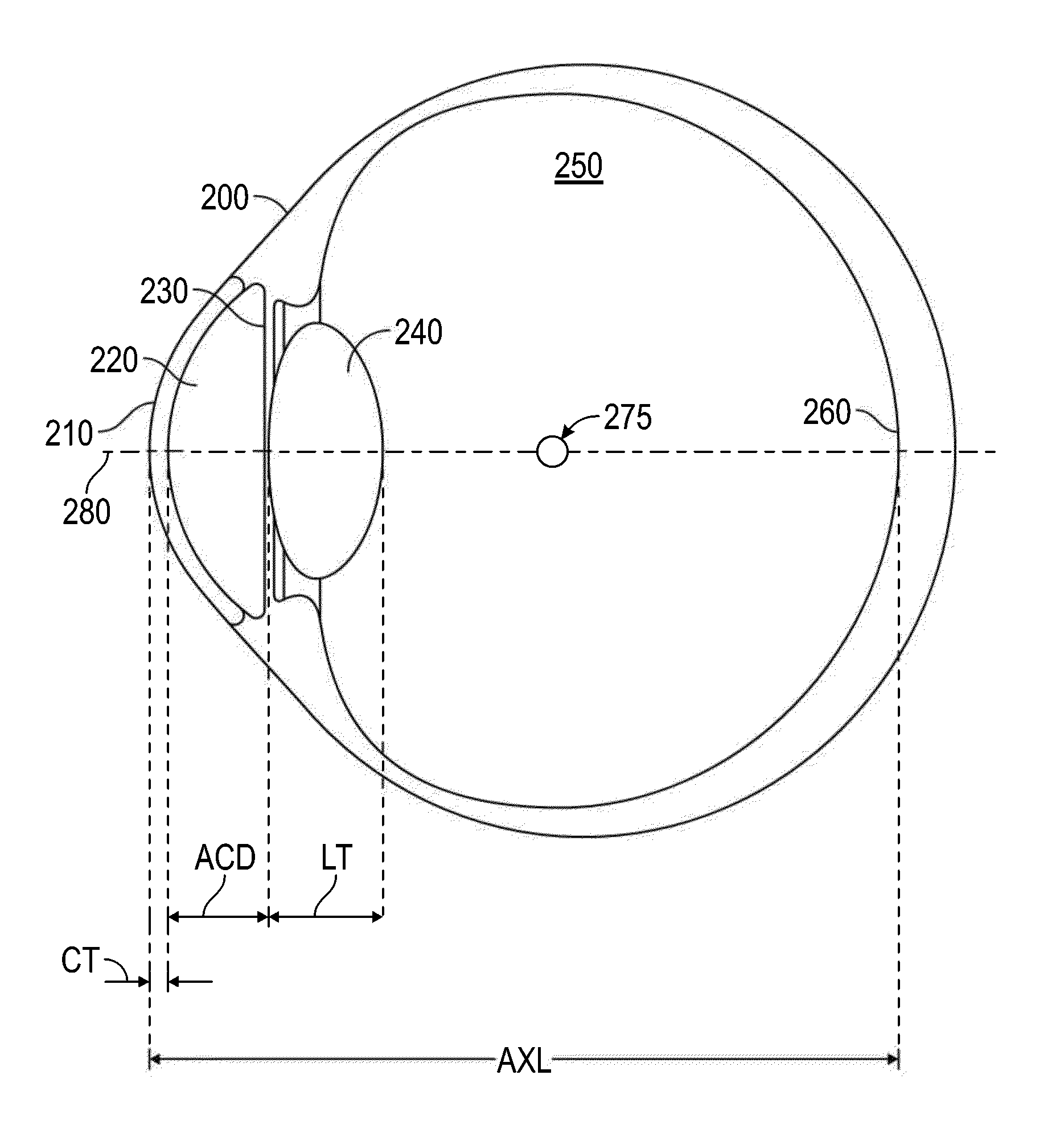
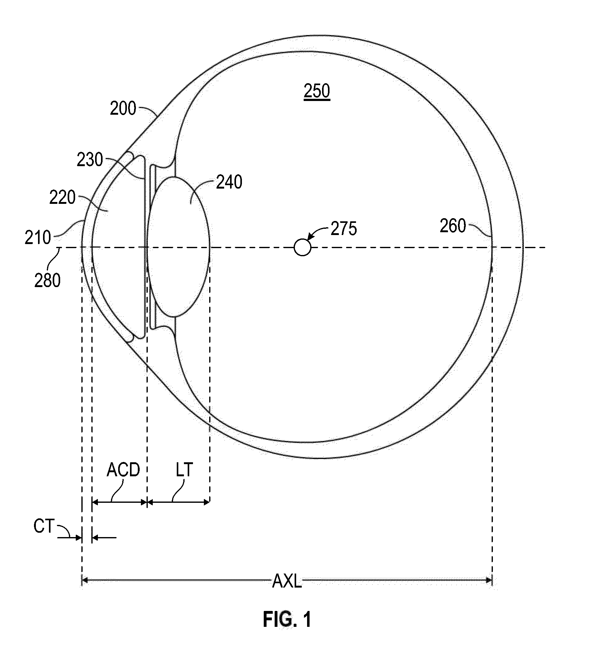
[0031]Another aspect of the subject matter disclosed herein includes a power calculation diagnostic procedure that measures corneal topography, eye length, retinal curvature, peripheral eye length, pupil position, capsular position, or any combination thereof in order to determine characteristic of the intraocular lens device that improves visual acuity and contrast sensitivity for patients with central visual field loss.
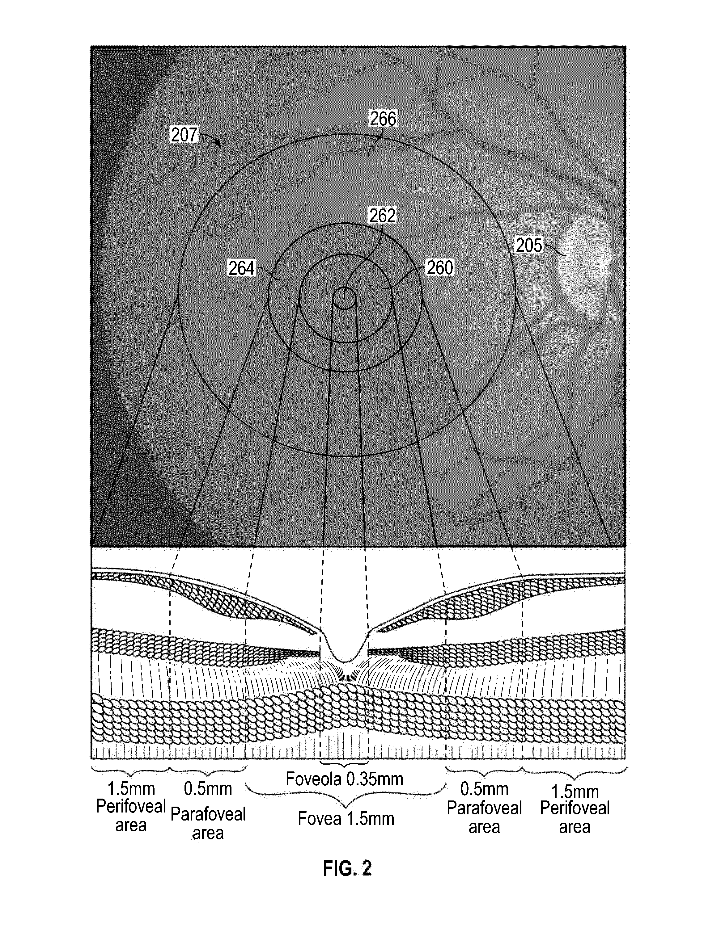
[0032]Implementations of intraocular devices described herein can include one or more optics with a large optical zone. The implementations of intraocular devices described herein are configured to focus obliquely incident light in a location of the peripheral retina at an eccentricity between about 5-25 degrees (e.g., eccentricity of 10 degrees, eccentricity of 15 degrees, eccentricity of 20 degrees, etc.). For patient with a well-developed preferred retinal location (PRL), various implementations of the intraocular device can be configured to focus incident light at the PRL. For patients without a well-developed PRL, the implementations of intraocular device described herein can help in the formation of the PRL.

Problems solved by technology

A patient with AMD suffers from a loss of vision in the central visual field due to damage to the retina.
However, such IOLs may not provide increased contrast sensitivity.

Method used


Image

  • Enhanced toric lens that improves overall vision where there is a local loss of retinal function
  • Enhanced toric lens that improves overall vision where there is a local loss of retinal function
  • Enhanced toric lens that improves overall vision where there is a local loss of retinal function

Examples


example iol

Design System

[0104]FIG. 8 illustrates a block diagram of an example IOL design system 27000 for determining properties of an intraocular lens configured to improve vision at a peripheral retinal location. The IOL design system 27000 includes a controller 27050 and a computer readable memory 27100 coupled to the controller 27050. The computer readable memory 27100 can include stored sequences of instructions which, when executed by the controller 27050, cause the IOL design system 27000 to perform certain functions or execute certain modules. For example, a PRL location module 27150 can be executed that is configured to determine a location of one or more PRLs for a particular patient. As another example, a deflection module 27200 can be executed that is configured to determine a deflected optical axis which intersects the determined PRL location at the retina. As another example, an IOL modification module 27250 can be executed that is configured to determine properties of the IOL w...


PUM


Abstract

Systems and methods are provided for improving overall vision in patients suffering from a loss of vision in a portion of the retina (e.g., loss of central vision) by providing an enhanced toric lens which redirects and/or focuses light incident on the eye at oblique angles onto a peripheral retinal location. The intraocular lens can include a redirection element (e.g., a prism, a diffractive element, or an optical component with a decentered GRIN profile) configured to direct incident light along a deflected optical axis and to focus an image at a location on the peripheral retina. Optical properties of the intraocular lens can be configured to improve or reduce peripheral errors at the location on the peripheral retina. One or more surfaces of the intraocular lens can be a toric surface, a higher order aspheric surface, an aspheric Zernike surface or a Biconic Zernike surface to reduce optical errors in an image produced at a peripheral retinal location by light incident at oblique angles.

Description

CROSS-REFERENCE TO RELATED APPLICATIONS[0001]This application claims benefit under 35 U.S.C. §119(e) of U.S. Provisional Application No. 61 / 950,757, filed on Mar. 10, 2014, titled “INTRAOCULAR LENS THAT IMPROVES OVERALL VISION WHERE THERE IS A LOSS OF CENTRAL VISION.” This application also claims benefit under 35 U.S.C. §119(e) of U.S. Provisional Application No. 61 / 987,647, filed on May 2, 2014. The entire content of each of the above identified applications is incorporated by reference herein in its entirety for all it discloses and is made part of this specification.[0002]This application is also related to U.S. application Ser. No. ______, filed concurrently herewith on Mar. 10, 2015, titled “INTRAOCULAR LENS THAT IMPROVES OVERALL VISION WHERE THERE IS A LOCAL LOSS OF RETINAL FUNCTION,” Attorney Docket No. AMOLNS.055A4. This application is also related to U.S. application Ser. No. ______, filed concurrently herewith on Mar. 10, 2015, titled “DUAL-OPTIC INTRAOCULAR LENS THAT IMPR...

Claims


Application Information

Patent Timeline
Patent Type & Authority Applications(United States)
IPC IPC(8): A61F2/16
CPCA61F2/1654A61F2/1613A61F2240/002A61F2/1637A61F2/1656A61F2/1602A61F2/1618A61F2/164A61F2/1645A61B3/14A61F2/1648A61F2002/1681A61B3/028A61F2/1605A61B3/0025A61B3/1005A61B3/103A61B3/107A61F2/1659
Inventor ROSEN, ROBERTWEEBER, HENDRIK A.CANOVAS VIDAL, CARMENVAN DER MOOREN, MARRIESELLITRI, DORA
Owner AMO GRONINGEN
Why Eureka
Try Eureka