Devices, systems and methods for passive control of flow

a passive control and flow technology, applied in the direction of air-flow influencers, mechanical equipment, transportation and packaging, etc., can solve the problems of large errors on a distant target, serious flow problems, and electromagnetic energy induced alarms

Active Publication Date: 2015-09-10
GENERAL ATOMICS AERONAUTICAL SYSTEMS
View PDF20 Cites 16 Cited by
  • Summary
  • Abstract
  • Description
  • Claims
  • Application Information

AI Technical Summary

Problems solved by technology

Aberrations in electromagnetic energy induced by unfavorable fluid flow are a serious concern in systems that operate in flow fields.
An electromagnetic beam in a flow field generally encounters flow in the vicinity of the instrument that is detrimental to successful operation of the instrument.
A small initial deformation of the wavefront can lead to large errors on a distant target.
The consequences of such deformations include beam deflection (bore-sight error) and jitter, beam spread, and loss of intensity.
Wavefront distortions can also cause reductions of resolution, contrast, effective range, and / or sensitivity for airborne electro-optical sensors and imaging systems.
However, these approaches are invasive, require complex sensors and systems, and / or necessitate alterations to the structure of the vehicle containing the housing.
Further, these approaches limit the utility of the instruments.
For instance, the orientations of the instrument with respect to the freestream flow, for which the instrument will successfully operate, are limited.
As an example, approaches that employ active control with static jets of fluid limit the viewing angles of the instrument because the flow from the jets is at a different angle relative to the flow over the instrument after the instrument has rotated.
While the jets themselves may move to compensate for the moving instrument, this introduces even further complexity and cost.

Method used


Image

  • Devices, systems and methods for passive control of flow
  • Devices, systems and methods for passive control of flow
  • Devices, systems and methods for passive control of flow

Examples


Embodiment Construction

” one will understand how the features of the embodiments described herein provide advantages over existing approaches to flow control.

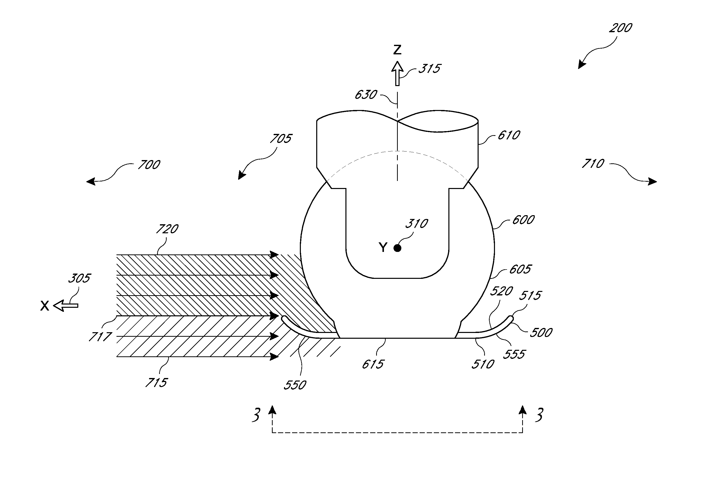
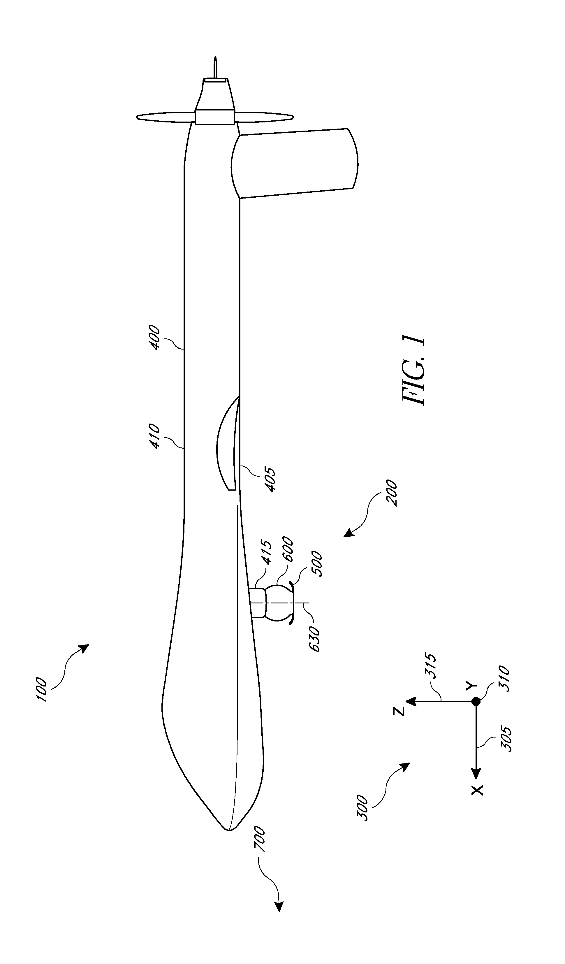
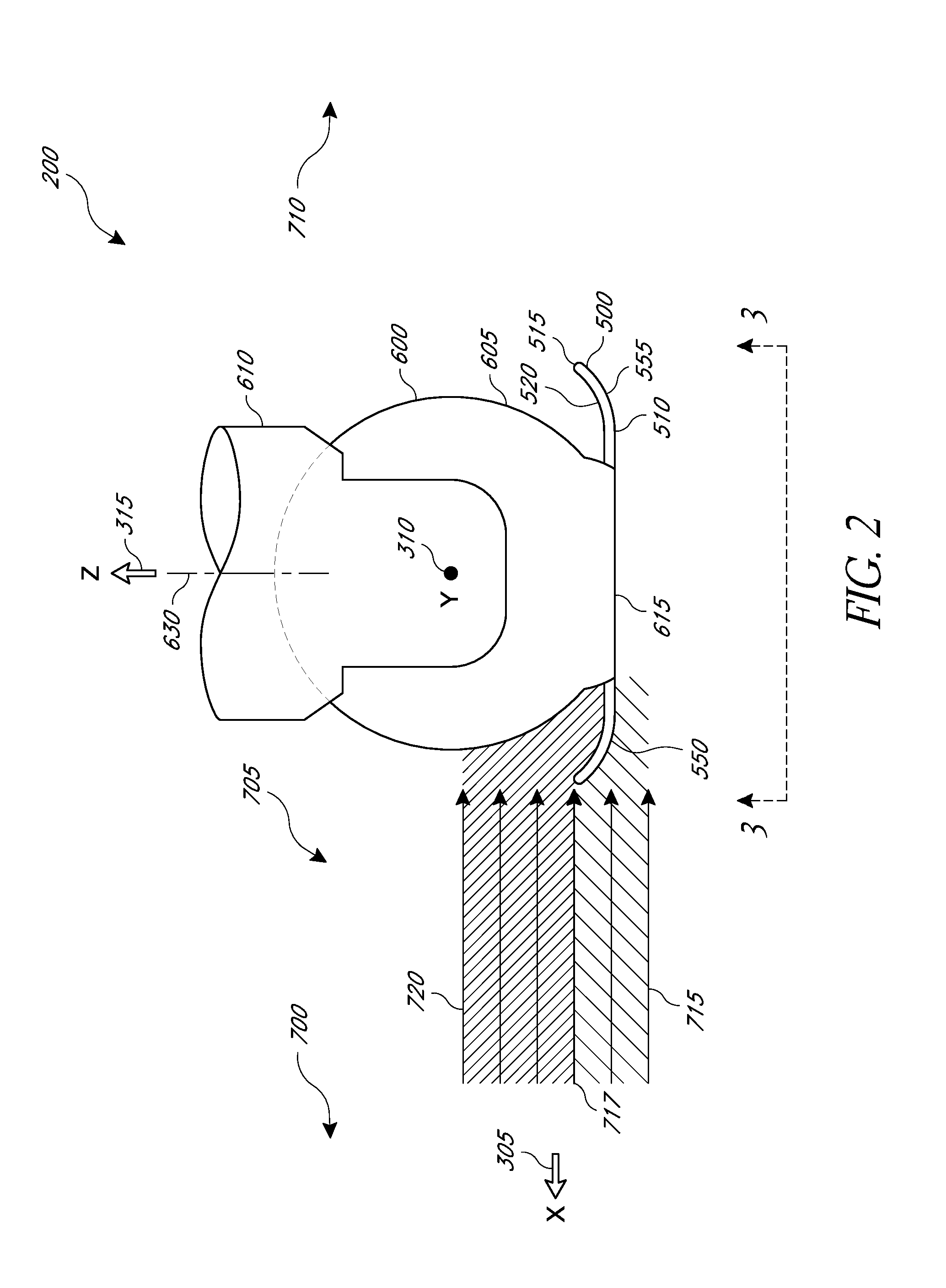
[0010]Several embodiments are disclosed for an apparatus for controlling fluid flow over a window of a moveable optical instrument housing, the housing comprising a perimeter and at least partially protruding from a vehicle into a freestream flow field. The apparatus may comprise an inner perimeter configured to complement the perimeter of the housing, an arcuate top surface comprising a curvature and configured to extend into an upstream portion of the freestream flow field, and an arcuate outer perimeter coupled to the arcuate top surface. The apparatus is configured to couple with the housing and to split the freestream flow field into a first flow field that is at least partially above the apparatus and window and a second flow field that is at least partially under the apparatus and around the housing. The first flow field comprises an aero-opti...


PUM


Abstract

Systems, devices and methods are disclosed for controlling the flow of a fluid over the window of an optical instrument housing in a freestream flow field. For example, the flow upstream of the housing may be split to create a flow region over the window that is conducive to successful operation of the instrument. The flow region may be maintained for various rotations of the housing about yaw, pitch, and roll axes. The disclosed features in some embodiments induce flow regions with reduced spatial and temporal density gradients of the flow over the window.

Description

INCORPORATION BY REFERENCE TO ANY PRIORITY APPLICATIONS[0001]Any and all applications for which a foreign or domestic priority claim is identified in the Application Data Sheet as filed with the present application are hereby incorporated by reference under 37 CFR 1.57.BACKGROUND[0002]1. Field of the Invention[0003]This disclosure relates generally to the field of instrumentation in freestream flow fields. In particular, features for improving the flow over an optical instrument in a freestream flow field are disclosed.[0004]2. Description of the Related Art[0005]Aberrations in electromagnetic energy induced by unfavorable fluid flow are a serious concern in systems that operate in flow fields. For instance, in some airborne communication and imaging systems, an optical beam is required to be transmitted through a relatively long distance, over which the quality of the beam can degrade due to variations of the index of refraction along its path. For air and many fluids, the refracti...

Claims


Application Information

Patent Timeline
Patent Type & Authority Applications(United States)
IPC IPC(8): B64C1/00F15D1/12B64D43/00F15D1/00B64C7/00B64C21/00
CPCB64C1/0009B64C7/00B64C21/00F15D1/12F15D1/003F15D1/0085B64D43/00B64C23/06Y10T137/2082Y10T137/2224Y02T50/10
Inventor ZERWECKH, SIEGFRIED HERMANNRUITH, MICHAEL RUDOLFRUTHER, STEVEN JAMESMODY, PRITESH CHETAN
Owner GENERAL ATOMICS AERONAUTICAL SYSTEMS
Why Eureka
Try Eureka